
Ducati Diavel Service Manual: Adjusting the front fork
The front fork used on this motorcycle has rebound, compression and spring preload adjustment.
This adjustment is done using the outer adjusters:
- Rebound damping;
- Inner spring preload;
- Compression damping.
Park the motorcycle in a stable position on its side stand.
Turn the adjuster (1) on fork leg top with a flat screwdriver to adjust rebound damping.
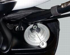
On the carbon model, adjustment is done using the knob (b) on the fork leg, without a screwdriver.
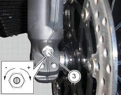
Turn the adjuster (3) on fork leg bottom with a flat screwdriver to adjust compression damping.
As you turn the adjusters (1) and (3), you will hear them click. Each click corresponds to different damping setting.
The stiffest damping setting is obtained with the adjuster turned fully clockwise to the "0" position. Starting from this position, turning counter clockwise, you can count the turns.
To change preload of the spring inside each fork leg, turn the hex. Adjuster (2) with a 22 mm hexagon wrench, starting from the fully open position (clockwise). From reference (a), every full turn clockwise corresponds to 1 mm of preload of the spring, up to a maximum of 15 mm, corresponding to 3 full turns.

Standard settings, from fully open position, are as follows: compression: 1 turn and a half; rebound: 1 and a half turns.
Spring preload: fully open (counter clockwise).
Important
Adjust both fork legs to same settings.
 Adjusting the position of the gear change and rear brake pedals
The position of the gear change and rear brake pedals in relation to the
footrests can be adjusted to suit the preferred
riding position.
To modify the gear change pedal position act in the foll ...
 Adjusting the rear shock absorber
The adjuster (1) located on the lower connection holding the shock absorber
to the swingarm adjusts the damping during
the rebound phase (return).
The knob (2), located on the left side of the m ...
Other materials:
Display background colour (automatic adjustment)
Instrument panel background colour is set automatically
according to exterior lighting conditions.
When sensor detects "poor lighting" (night), it switches to
black background mode; vice versa when a "significant"
lighting is detected (day), it switches to white background
...
Warranty
In your own interest, and in order to guarantee product
reliability, you are strongly advised to refer to a ducati dealer
or authorised service centre for servicing that requires any
particular technical expertise.
Our highly skilled staff have the tools required to perform any
servicing job ...
Reassembly of the front half-fairings
Fit the clips (2) on the front rh half-fairing (1).
Join the rh support (4) and the front rh half-fairing (1) and keep them in
position by starting the screws (5).
Note
To mount the rh support (4) in a proper way, it is necessary to insert the
tab (g) of the front rh half-fairing (1) in t ...