
Ducati Diavel Service Manual: Checking valve lift
Set the engine to the configuration described for the "checking and adjusting the valve clearances", previously indicated.
Position the tool 88765.1518 On the cylinder head: the part marked "a" should be on the intake side and the part marked "s" should be on the exhaust side.
Seat the plate (a) and tighten the screws (b).
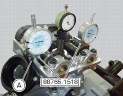
Set the opening valve clearance to zero when the camshaft is in its rest position by fitting a feeler gauge between the upper rocker arm and the opening shim.
Lock the dial gauge into the seat of the stand marked "a" and position the fork probe against the face of the closing shim.
Set the dial gauge to zero when the valve is fully closed.
Rotate the intake camshaft so as to allow the intake valves to lift fully.
Check on the dial gauge that the measured value corresponds to the prescribed one (sect. 3 -1.1, Timing system/valves).
Repeat the same operation for the exhaust valves, using the dial gauge in the support seat 88765.1518 With the marking "s".
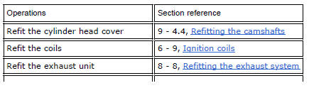
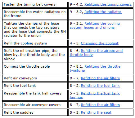
Refit the components by carrying out the same operations indicated in chapter "checking and adjusting the valve clearances", previously described.
Refit the components removed in the procedure.
 Checking and adjusting the valve clearances
Note
For clarity, the figures show the engine removed from the frame.
Move the piston of the cylinder being checked to tdc of the power stroke: in
this condition, all the valves are closed and ...
 Checking the engine timing
Set the engine to the configuration described for the "checking and adjusting
the valve clearances", previously indicated.
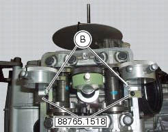
Install tool 88765.1188 (G) in the spark plug bore to determine the ...
Other materials:
Checking the coolant level
To the specified intervals in the "scheduled maintenance chart" (sect. 4 - 2)
Check the coolant level contained in
the expansion reservoir, on the right side of the vehicle.
The coolant level must be between the max. And min marks on the tank.
If the level is low, top up with the recommende ...
Removal-refitting of the engine assembly
Screw
Special screw
Nut
Screw
Swingarm pivot
Special screw
Washer
Spare parts catalogue
Diavel abs frame
Diavel abs swingarm
Diavel carbon
abs
frame
Diavel carbon
abs
swingarm
Important
Bold reference numbers in this section identify parts not shown in the
figures a ...
Steering head: front fork
Screw
Screw
Steering head
Bottom yoke
Left fork leg assembly
Right fork leg assembly
Counter nut
Damper assembly
Bush
Spring
Preload tube
Collar
Washer
Top cap assembly
Screw
Washer
Adjuster screw
Special washer
Fork tube + calliper unit
Dust cap
Sealin ...