
Ducati Diavel Owners Manual: Backlighting setting function for the instrument panel on Handlebar - dashboard 2
This function allows backlighting setting of the instrument panel on handlebar.
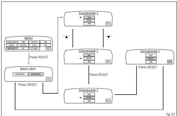
To access the function it is necessary to view the "setting" menu page 48, using
button (1, fig. 14) ?"
" or (2, fig. 14) ?" " select the "back light" function
and press the reset
button (12, fig. 12) To go to next page.
Use button (1, fig. 14) ?" " or (2,
fig. 14) ?" " to select the
"dashboard 2" function and confirm by pressing the
reset button (12, fig. 12).
Once you enter the "dashboard 2" function, setting is highlighted on the display
(max, middle or min in green); use button (1, fig. 14) ?"
" or (2, fig. 14) ?" " to shift the
arrow on the left onto the new setting and confirm by
pressing the reset button (12, fig. 12).
To exit the setting function, press the reset button (12, fig.
12) Where "exit" is highlighted.
Select "max" setting and the background of the instrument panel on handlebar permanently sets backlighting to maximum power to improve readout view - recommended with bright exterior lighting.
Select "middle" setting and the background of the instrument panel on handlebar permanently sets reduced backlighting to 30% of its maximum power for dimmed visibility - recommended with poor exterior lighting.
Select "min" setting and the background of the instrument panel on handlebar permanently sets reduced backlighting to 50% of its maximum power for dimmed visibility - recommended with very poor exterior lighting and/or dark.
 Background setting function for the instrument panel on tank - dashboard 1
This function allows setting the "background" of the
instrument panel on tank.
To access the function it is necessary to view the "setting" menu page 48, using
button (1, fig ...
 Digital rpm indication function
This function displays the number of rpms for improved
accuracy when setting idle rpm.
To access the function it is necessary to view the "setting" menu page 48, using
button (1, fig. ...
Other materials:
Reassembling the frame and the lateral footrests
Apply the recommended grease to the thread of the pins (9) and of the nuts
(8).
Place the frame (1) and the brackets (2) and (3) on the engine block. Start the
pins (9) by holding the nuts (8) and insert
without tightening the screws (6) into the adjusters (4).
Position and fix the rear s ...
Recovery procedure in the event of electric steering lock fault
If any fault occurs during activation of the electric steering lock: for
example, if the pin jams, if the handlebar is moved
while the pin is deployed or if there is excessive strain on the electric pin
actuator motor, the electric steering lock is
automatically disengaged and the hands free s ...
Overhauling the front brake components
Important
Critical safety components. The brake calliper manufacturer recommends
that you do not attempt to service the internal
components of the brake callipers. Incorrect overhaul of this component could
endanger rider safety.
Operations should be limited to renewal of the pads, fasteners ...