
Ducati Diavel Owners Manual: Charging the battery
Before charging the battery, it is recommended to remove it from the motorcycle.
 Important
The battery is housed in the cowling, always contact a ducati dealer or an authorised service centre for its removal.
Remove the left cowling (1, fig. 137) Loosening: side screw (2, fig. 137) Retaining the electrical parts box; top screw (3, fig. 137) Retaining the electrical parts box; bottom screw (4, fig. 137) Retaining the central cowling;
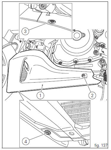
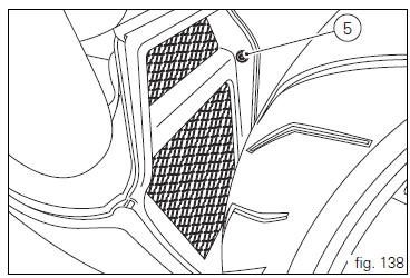
Screw (5, fig. 138) Retaining the central cowling to left cowling.
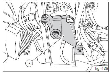
Unscrew the screws (6, fig. 139) And remove the battery mounting cover (7, fig. 139).
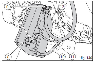
Slide out the battery (8, fig. 140) From its housing and, always starting from the negative terminal (-), loosen the screws (9, fig. 140).
Remove the positive cable (10, fig. 140), The abs positive cable (11, fig. 140) From the positive terminal and the negative cable (12, fig. 140) From the negative terminal.
 Warning
The battery produces explosive gases: keep it away from heat sources and flames.
 Warning
Keep the battery out of the reach of children.
Charge the battery at 0.9 A for 5÷10 hours.
Charge the battery in a well-ventilated area.
Connect the battery charger leads to the battery terminals: red to the positive terminal (+), black to the negative terminal (-).
 Important
Connect the battery to the charger before switching it on; failure to do so can result in sparking at the battery terminals, which could ignite the gases inside the cells.
Always connect the red positive terminal (+) first.
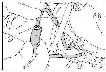
Lay down the abs positive cable (11, fig. 141), Onto positive cable (10, fig. 141) And start screw (9, fig. 141) In its thread on these cables.
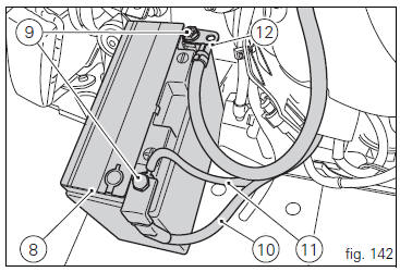
Connect the positive cable (10, fig. 142), Previously assembled to abs cable (11, fig. 142), To battery positive terminal, and negative cable (12, fig. 142) To battery negative terminal, by starting the other screw (9, fig. 142) In its thread.
Tighten the terminal clamp screws (9, fig. 142) To a torque of 5 nm ±10% and apply grease onto the battery terminals to prevent oxidation.
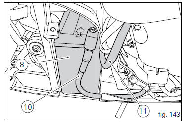
Reposition the battery (8, fig. 143) In the support, positioning the cables (10, fig. 143) And (11, fig. 143) As shown in fig.
143.
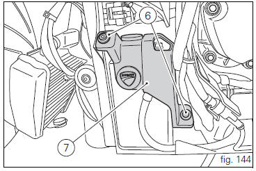
Refit battery mounting cover (7, fig. 144) And fasten tightening the screws (6, fig. 144) To a torque of 10 nm ±10%.
Refit the left cowling (1, fig. 145) As follows: start the side screw (2, fig. 145) Retaining the electrical parts box in its thread; start the top screw (3, fig. 145) Retaining the electrical parts box in its thread; start the bottom screw (4, fig. 145) Retaining the central cowling in its thread;
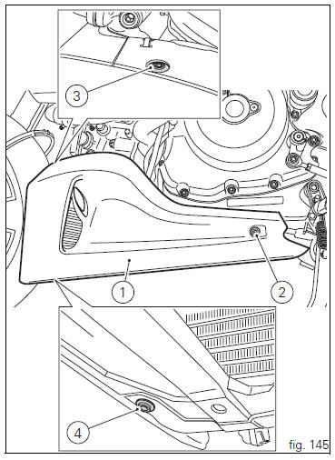
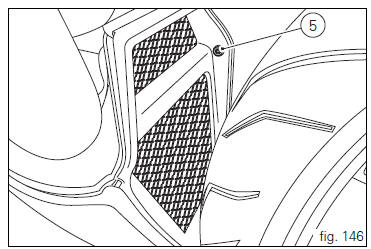
Start the screw (5, fig. 146) Retaining the central cowling to left cowling in its thread.
Tighten the screws (2, fig. 149), (3, Fig. 145), (4, Fig. 145) And (5, fig. 146) To a torque of 10 nm ±10%.
 Adjusting throttle control free play
The throttle twistgrip must have free play of 1.5×2.0 Mm in
all steering positions, measured on the outer edge of the
twistgrip. If necessary, adjust it using the adjusters (1 and 2,
fig. 135 ...
 Charging and maintenance of the battery during winter Storage
Your motorcycle is equipped with a connector (1, fig. 147) To
which you can connect a special battery charger available
from our sales network.
...
Other materials:
Refitting the gear interlock plunger and pawl assembly
On the special screw (3), fit the gear pawl lever (4), orienting it as shown
in the figure, the washer (2) with the square
edge side (d) facing the clutch-side crankcase half, and the spring (1),
positioning it so that the hook end (a) is facing
the gear pawl lever. Locate the hook end (a) of ...
Engine setting function (engine power control)
This function customises engine power and output.
To access the function it is necessary to view the "setting" menu page 48, using
button (1, fig. 14) ?"
"or (2, fig. 14) ?" "select the "riding mode"function
and press the
reset button (12, fig. 12) T ...
Stands
Side stand
Side stand switch
Screw
Plate
Screw
Inner spring
Outer spring
Nut
Rotation pivot
Screw
Screw
Screw
Nut
Clearance adjuster
Spare parts catalogue
Diavel abs stand
Diavel carbon
abs
stand
Important
Bold reference numbers in this section identify part ...