
Ducati Diavel Service Manual: Checking valve clearances
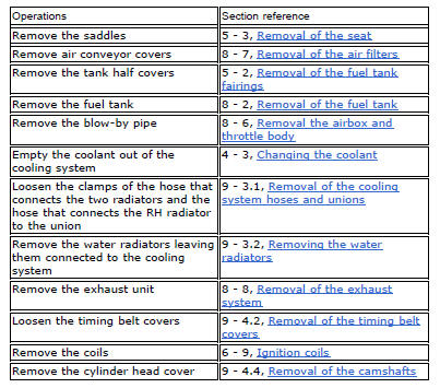
To check the valves clearance, it is necessary to have access to the cylinder head covers and then remove the components listed below.
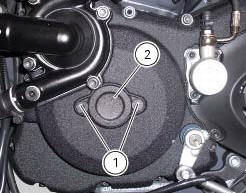
Unscrew the two fixing screws (1) of the cover (2) according to the crankshaft.

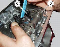
Fit the tool handgrip 88713.0123 In the holes of the generator cover to be able to turn the crankshaft so that the valve on which the control is carried out is in rest position.
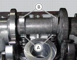
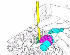
With the valve in the rest position, slide a feeler gauge between rocker arm (a) and the lowest side of the cam (b) to measure the clearance.
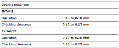
The clearances must be within the specified limits:
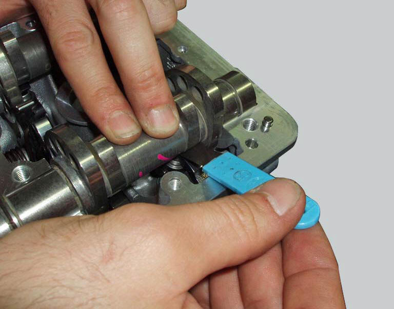
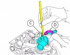
With the valve in the rest position, slide a feeler gauge between closing
rocker arm (c) and the highest side of the cam
(d) to measure the clearance. 
If detected values exceed the specified limits, replace opening and/or closing shims, as described in paragraph "removing the valves" (sect. 9 - 4.5), With an adequate height to obtain the specified clearance.
Note
Opening rocker arm shims measuring from 1.8 To 3.45 Mm and closing rocker arm shims measuring from 2.2 To 4.5 Are available as spare parts. The size is punched on the shim.
Remove the handgrip tool 88713.0123 From the hole of the generator cover.
Make sure that the o-ring (3) is fitted on the cover (2).
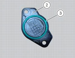
Refit the external cap (2) by tightening the two retaining screws (1) to a torque of 10 nm (min. 9 Nm - max. 11 Nm) (sect. 3 - 3, Engine torque settings).
Change timing belts
To replace the timing system belts follow the procedures described in paragraph "removal of the movable tensioner/timing belt" and "refitting the timing belts" (sect. 9 - 4.2).
 Changing the engine oil and filter cartridge
Note
This operation has to be carried out with hot engine (but turned off)
because the oil in these conditions is more fluid and
its evacuation is faster and complete.
Remove the drain plug (3) w ...
 Spark plugs replacement
Check the colour of the ceramic insulation around the central electrode:
an even, light brown colour indicates the engine is in good condition and
running at the right temperature.
Inspect the c ...
Other materials:
Checking and adjusting the valve clearances
Note
For clarity, the figures show the engine removed from the frame.
Move the piston of the cylinder being checked to tdc of the power stroke: in
this condition, all the valves are closed and
the timing shafts come in neutral position and, therefore, free to rotate; check
to the valve cl ...
Refitting the crankshaft/connecting rod assembly
Install the connecting rod assembly (6) and (2) in the crankcase, carry out
the shimming and crankcase half reassembly
procedure as described in sect. 9 - 9.2, Reassembly of the crankcase halves.
Important
Make sure that the connecting rods (2) are correctly positioned in the
cylinders. Incor ...
Solenoid starter
Remove the protection cover (a).
Undo the screws (2), taking care to collect the spring washers (3).
Remove the starter motor-solenoid cable (4) and the solenoid-battery cable (5).
Remove the starter solenoid (1) sliding it upwards.
Checking operation of the starter solenoid
To ...