
Ducati Diavel Service Manual: Refitting the swingarm
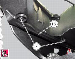
Apply the recommended threadlocker to the screws (7).
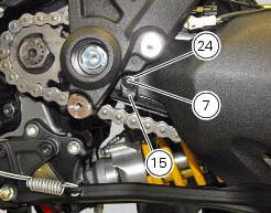
Install the lower chain guard (15) on the swingarm (8), fastening it with the screws (7): tighten the screws (7) to a torque of 4 nm +/- 10% (sect. 3 - 3, Frame torque settings).
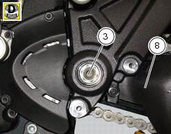
Locate the swingarm (8) on the frame.
Lubricate with recommended grease the swingarm shaft (1) with the screw (3) and insert it fully home on the frame and through the brackets (36).
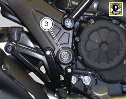
On the bike opposite side fix the swingarm shaft (1) with the screw (3) after having lubricated it with recommended grease, and fit the washer (2) between frame and swingarm.
Tighten the screw (3) to the torque of 72 nm +/- 5% (sect. 3 - 3, Frame torque settings).
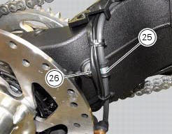
Position the rear brake hose, the rear speed sensor cable, and the rear wiring on the swingarm, by starting the screws (26) of the cable grommet (25).
Tighten the screw (26) to a torque of 8 nm +/- 10% (sect. 3 - 3, Frame torque settings).
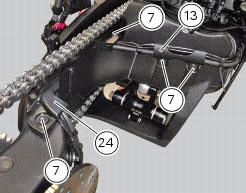
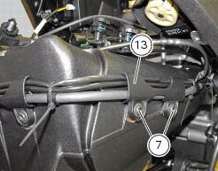
Refit the upper chain slider (24) and the hose guide (13) and tighten the screws (7) to a torque of 4 nm +/- 10% (sect. 3 - 3, Frame torque settings).
Refit the rear wheel eccentric hub as described in chapter "refitting the rear wheel eccentric hub and rear wheel shaft" of this section.
 Overhauling the rear swingarm
Inside the swingarm (8), in correspondence with the pivot point on the frame,
there is a pair of ball bearings (10) and a
spacer (11) on the rh side, and a pair of roller bearings (6), with sealing ...
 Final drive
Circlip
Nut
Washer
Nut
Rear sprocket flange
Cush drive bush
Inner ring
Chain
Spacer
Chain cover
Screw
Nut
Lock washer
Front sprocket
Spacer
O-ring
Rear sprocket
...
Other materials:
Checking and overhauling the components
Clearance between the clutch drum and friction plates
Insert a friction plate (e) in the clutch drum (f) and measure the clearance
(s) with a feeler gauge.
Clearance "s" must not exceed 0.6 Mm.
If it does, renew the plates and, if necessary, the clutch drum.
Overhaul of the clutch plat ...
Dashboard menu option scrolling not possible
Fault codes
Dds: no fault code displayed
Dashboard: no fault code displayed
Location of connections and components
Location of left hand handlebar switchgear set connection.
Pin numbering for wiring harness side dashboard connector. ...
External components
Oil breather valve
O-ring
Sealing washer
Gear position sensor
Cylinder barrel/head stud
Nipple
By-pass spring
Plug
Plug
Aluminium gasket
Nut
Lock washer
Timing gear pair
Key
Key
O-ring
Screw
Locating dowel
Starter idler gear
Washer
Gear shaft
O-ring
...