
Ducati Diavel Service Manual: Disassembly of the clutch cover
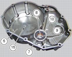
Remove the plug (14) and its o-ring (13), the plug (17) and its o-ring (15) from the cover.
Undo the fixing screw (16) of the inner cover (19).
Remove the inner cover (6) and soundproofing panel (18).
Remove the circlip (10) and withdraw the shim (9) and the sealing ring (8).
The drilled bush (7) is mounted to the cover by a forced interference fit. Remove it using a suitable puller.
Inspect the sealing ring (8) and renew it if necessary.
 Removal of the clutch-side crankcase cover
Unscrew the screws (2), (3) and (5) securing the clutch-side crankcase cover
(1).
Tap around the edge of the cover with a plastic mallet to detach it from the
crankcase half.
Remove th ...
 Reassembly of the clutch-side crankcase cover
Fit the plug (14) and the gasket (13). Fit the plug (17) and the gasket (15).
If the bush has been replaced, fully seat the new bush (7) in the slot in the
cover using a suitable drift and a pr ...
Other materials:
Removal of the expansion tank
Loosen the clamp (6), open the hose guide (a) and slide the hose (7) out of
the radiator.
Open clamps (14) and release the hoses that pass through them.
Loosen the screws (16).
Remove the tank (12) with its hoses (7) and (20) and the support (15).
Loosen the clamp (19) to r ...
Exhaust system
Screw
Bush
Vibration damper mount
Silencer
Washer
Screw
Bracket
Nut
Nut
Upper heat guard
Screw
Washer
Central heat guard
Spacer
Clip nut
Long exhaust spring
Plug
Sealing washer, thickness 1
Vertical exhaust pipe
Lambda sensor
Nut
Vertical flange
Exh ...
Adjusting the front fork
The front fork used on this motorcycle has rebound,
compression and spring preload adjustment.
The settings are adjusted using external adjuster screws.
To adjust rebound damping (fig. 109);
To adjust spring preload (fig. 109);
To adjust compression damping (fig. 110).
Park the mo ...