
Ducati Diavel Owners Manual: Menu 2 on/off function
This function turns off and back on the menu 2.
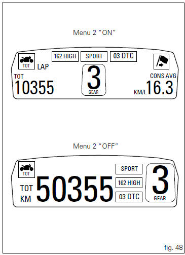
If menu 2 is disabled, the functions for average fuel consumption (cons.Avg), instantaneous fuel consumption (cons.), Average speed (speed avg), trip time (trip time) and air temperature (air) will no longer be displayed in the "main screen". Nevertheless, all these functions will keep on their counters so that when menu 2 is re-enabled data will be updated and consistent.
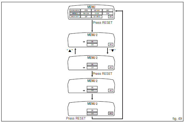
To access the function it is necessary to view the "setting" menu page 48,
using button (1, fig. 14) ?"
" or (2, fig. 14) ?" " select the "menu 2" function and
press the reset
button (12, fig. 14) To go to next page.
Function state is highlighted on the display (on in green or off in yellow); use
button (1, fig. 14) ?"
" or (2, fig. 14) ?"  "
"
to shift the arrow on the left onto the new setting and
confirm by pressing the reset button (12, fig. 12).
To exit the setting function, press the reset button (12, fig.
12) Where "exit" is highlighted.
 Default function (resetting ducati default parameters)
This function resets the parameters set by ducati for each
riding style.
To access the function it is necessary to view the "setting" menu page 48, using
button (1, fig. 14) ?"
...
 Background setting function for the instrument panel on tank - dashboard 1
This function allows setting the "background" of the
instrument panel on tank.
To access the function it is necessary to view the "setting" menu page 48, using
button (1, fig ...
Other materials:
Timing system
Central external cover
Air filter
Horizontal cylinder timing belt cover
Screw
Filter support
Screw
Washer
Nut
Tensioner pulley assembly
Circlip
Camshaft pulley
Tensioner pin
Idler pulley assembly
Timing belt
Nut
Key
Spacer
Camshaft pulley
Driveshaft pulley ...
Removal of the fuel tank fairings
Remove the rh air inlet (7) by loosening screws (6) and (9).
Undo the retaining screw (3) of the rh front half-fairing (1).
Slightly pull the pin (a) to disengage it from the seal (b), and remove the
rh front half-fairing (1) by sliding it onwards
and releasing the tabs (c) from the ...
Horn not working
Fault codes
Dds: horn diagnosis -> short circuit to ground (s.C. Gnd).
Dashboard: the error "claxon" (horn) is shown on the service display. The eobd
warning light activates.
Wiring diagram
Db dashboard connection, s horn button. 5 Blue/white - b/w, 1 red/blue - r/b,
db 19 purple/bl ...