
Ducati Diavel Service Manual: Gearbox shafts
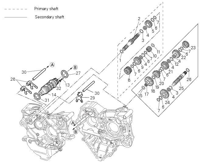
- Shim, thickness 1
- Gearbox primary shaft
- Shim, thickness 0.5
- Needle roller bearing
- 5Th speed driving gear
- Splined washer, thickness 0.5
- Circlip
- 3Rd- 4th speed driving gear
- 6Th speed driving gear
- 2Nd speed driving gear
- Shim, thickness 1.8
- Splined washer, thickness 0.5
- Special needle roller (square cross-section)
- Selector drum
- Shim washer
- Selector drum assembly
- Needle roller bearing
- 1St speed driven gear
- Shim, thickness 1
- 5Th speed driven gear
- 4Th speed driven gear
- 3Rd speed driven gear
- 6Th speed driven gear
- 2Nd speed driven gear
- Gearbox secondary shaft
- Shim washer
- Shim, thickness 1
- 1St, 4th- 2nd, 3rd speed selector fork
- 5Th, 6th speed selector fork
- Selector fork shaft
- Shim, thickness 1
- Needle roller retaining circlip (square cross-section)
Spare parts catalogue
Diavel abs gearchange control
Diavel abs gearbox
Diavel carbon abs gearchange control
Diavel carbon abs gearbox
Important
Bold reference numbers in this section identify parts not shown in the figures alongside the text, but which can be found in the exploded view diagram.
- Removal of the gearbox assembly
- Disassembly of the gearbox shafts
- Overhaul of the gearbox
- Inspection of the gear selector forks
- Inspection of the gear selector drum
- Reassembly of the gearbox shafts
- Reassembly of the gearbox
 Refitting the gear selector lever
Position the gearbox drum selector fork in the centre of the gear rollers.
Position the gear selector lever (21) together with control shaft, spring and
plate into the chain-side crankcase half.
...
 Removal of the gearbox assembly
Withdraw the selector fork shafts (30).
Move the forks (28) and (29) to disengage them from the slots in the selector
drum (14).
Withdraw the selector drum (16) taking care not to lose s ...
Other materials:
Instrument panel on tank
Menu 1 (tot, trip1, trip2, trip fuel).
Menu 2 (cons.Avg., Cons., Speed avg, air and
trip time) if active.
Gear / neutral indication.
Icon referred to the function below from menu 1.
Indication of engine setting for the currently set riding
style.
Currently set riding style (riding m ...
Removal of the clutch-side crankcase cover
Unscrew the screws (2), (3) and (5) securing the clutch-side crankcase cover
(1).
Tap around the edge of the cover with a plastic mallet to detach it from the
crankcase half.
Remove the clutch cover (1) paying attention to the centring bushing (12).
Check the condition of the cent ...
Fairings
Rh front half-fairing
Clip
Screw
Right-hand support
Screw
Screw
Rh air inlet
Lh air inlet
Screw
Clip
Left-hand support
Lh front half-fairing
Lh tank fairing
Screw
Nylon washer
Special screw
Washer
Spacer
Spring
Rubber pad
Rh tank fairing
Tank fairing
...