
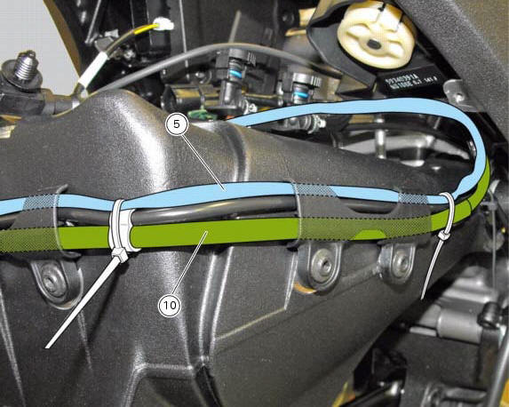
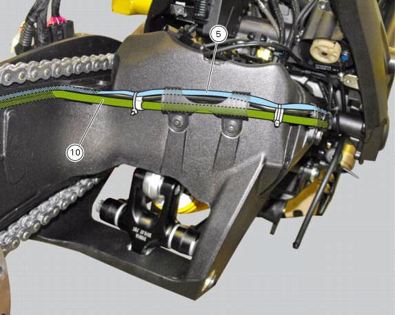
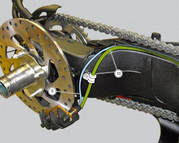
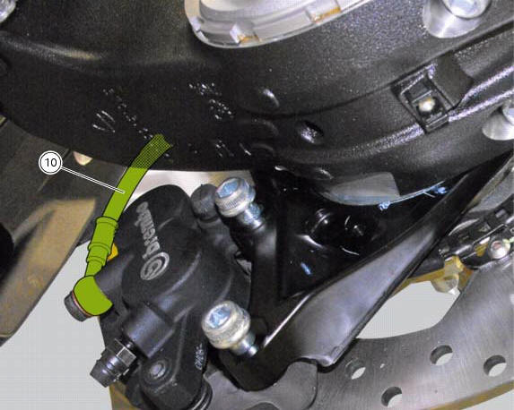
Ducati Diavel Service Manual: Flexible wiring/hoses positioning
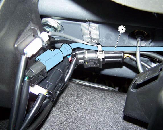
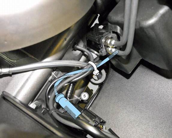
The routing of the abs wiring has been optimised to ensure the minimum obstruction.
Each section is designed to prevent interference with parts that might damage wires or cause operating failures when riding.
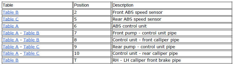
Table a
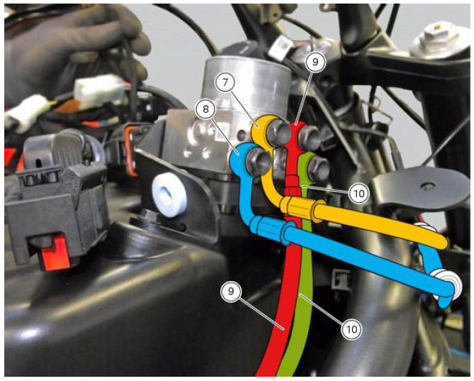
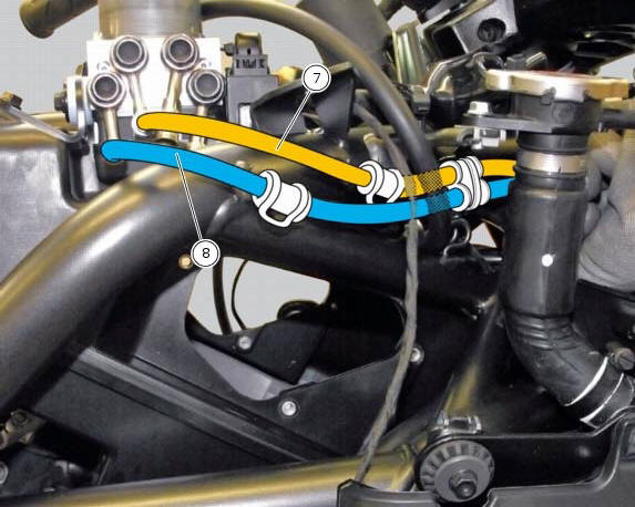
Table b
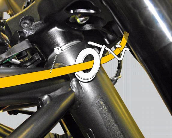
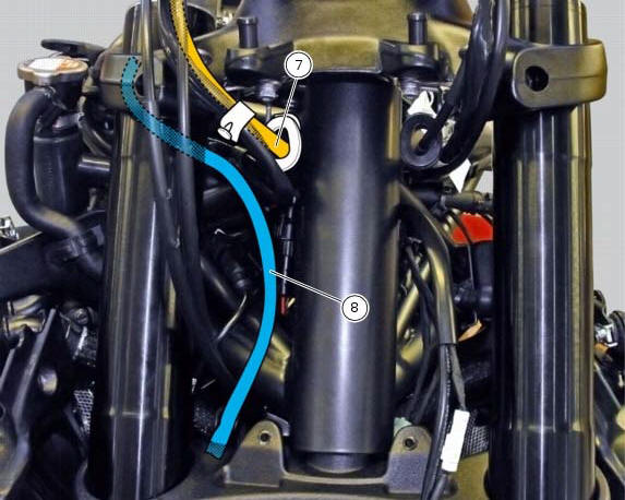
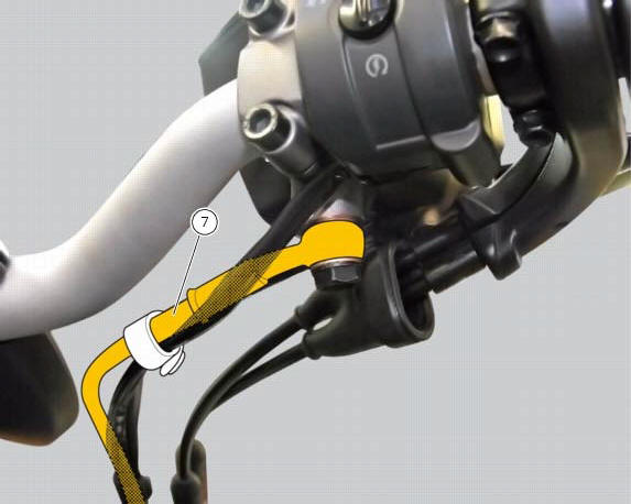
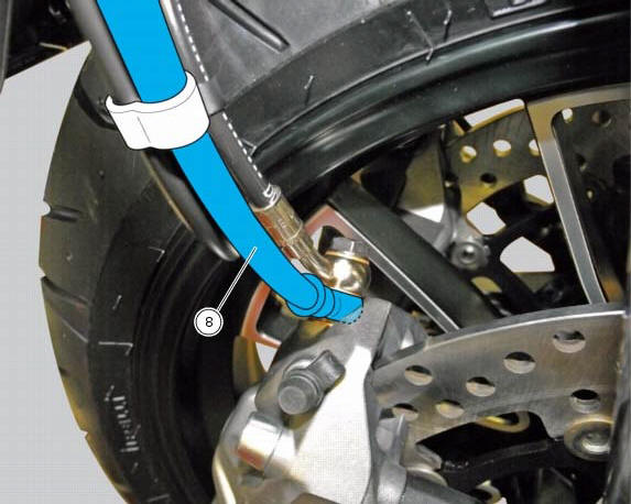
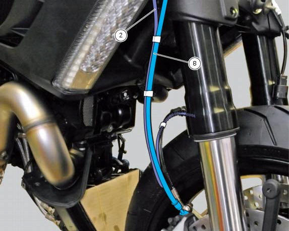
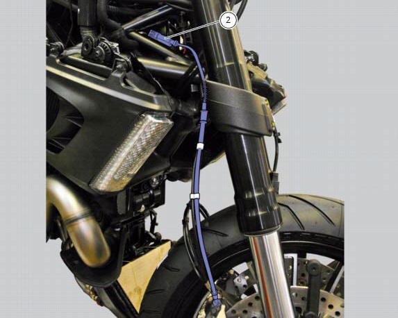
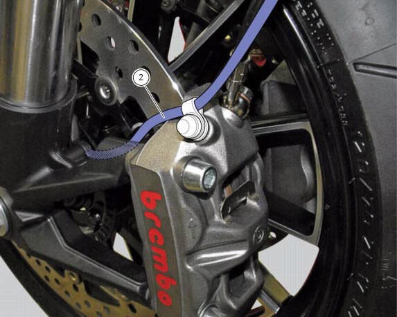
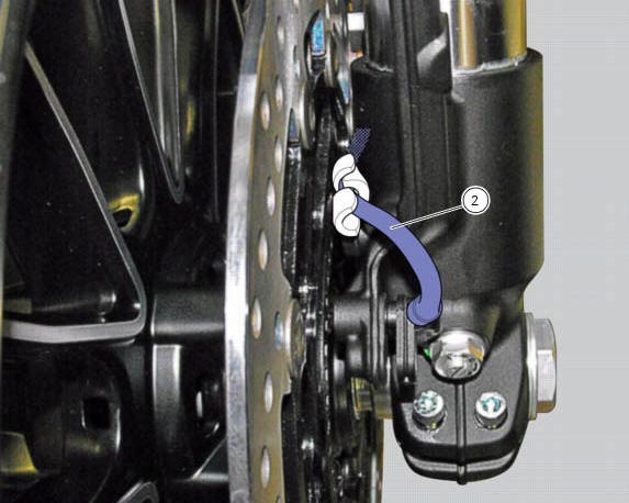
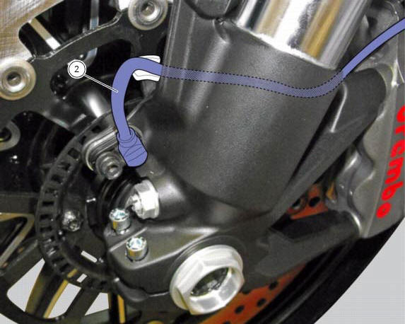
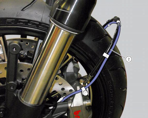
Table c
 Refitting the abs control unit
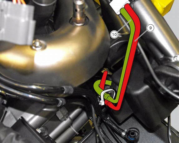
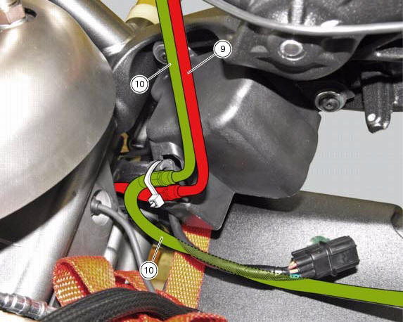
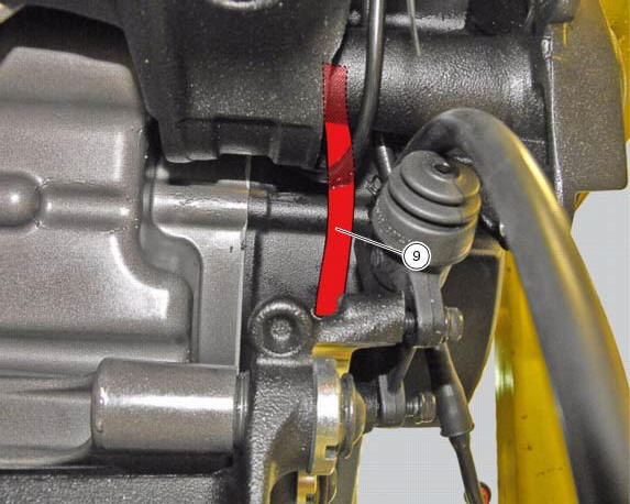
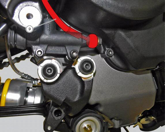
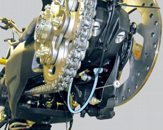
If the brake hoses (7), (8), (9) and (10) on the abs control unit are changed
or removed, ensure that the fittings on the
control unit are positioned correctly.
Warning
If incorrectly positioned, ...

Other materials:
Removal of the timing belt covers
Loosen the screws (4) securing the central external cover (1) and remove it
from the central side.
Undo the fixing screws (4) of the external cover (25) and remove it from the
vertical thermal unit.
Undo the fixing screws (4) of the external cover (3) and remove it from the
horizonta ...
Brakes
Separate-action anti-lock brake system operated by hall-type
sensors mounted to each wheel, with phonic wheel
detection: abs can be disabled.
Front
Semi-floating drilled dual disc.
Braking material:
steel.
Carrier material:
aluminium.
Disc diameter:
320 mm.
Hydraulically operated ...
Display background colour (automatic adjustment)
Instrument panel background colour is set automatically
according to exterior lighting conditions.
When sensor detects "poor lighting" (night), it switches to
black background mode; vice versa when a "significant"
lighting is detected (day), it switches to white background
...