
Ducati Diavel Owners Manual: Instrument panel diagnosis
This function identifies any abnormal vehicle behaviours.
The instrument panel activates any abnormal vehicle behaviours in real time (errors).
At key-on (at the end of the check) one or more "errors" are displayed in red (only if they are active).
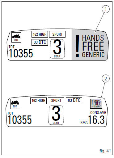
When an "error" is triggered, the indication (red) remains well visible for 10 seconds (1, fig. 41) Then becomes smaller (2, fig. 41).
If there are multiple errors, they will scroll automatically every 3 seconds. The "engine/vehicle diagnosis - eobd" light on instrument panel located on handlebar (7, fig. 4) Always turns on when one or more errors are activated.
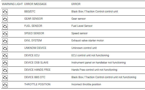
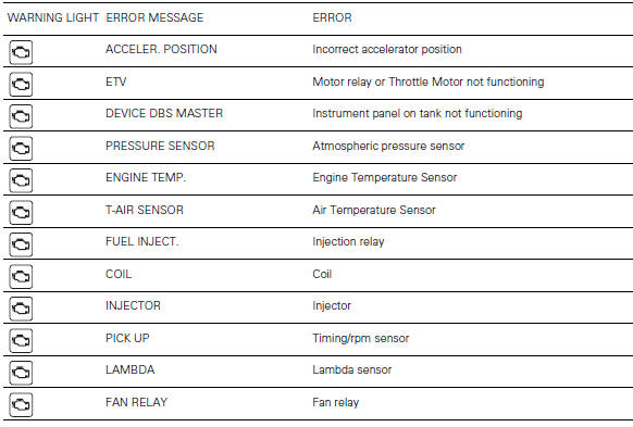
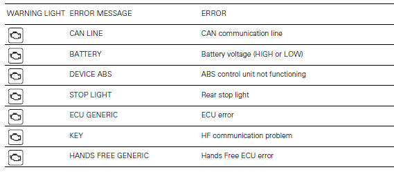
The table below shows the errors that can be displayed.
 Warning
When one or more errors are displayed, always contact a ducati dealer or authorised service centre.
 Steering release error - steering still locked
The activation of this (amber yellow) "warning" indicates
that the hands free system was not able to extract the
steering lock.
Warning
In this case, ducati recommends turning the vehic ...
 Setting menu
This menu is used to enable/disable and set some
motorcycle functions.
To access the "setting menu" press the button (2, fig. 14)
? for 3 seconds.
Note
When within this menu no ...
Other materials:
Removal of the rear brake calliper
Important
The brake manufacturer advises against any servicing of the internal
components of brake callipers or the master cylinder.
Incorrect overhaul of these critical safety components can endanger rider and
passenger safety.
Before removing the parts in question, you must first carry ou ...
Backlighting setting function for the instrument panel on Handlebar -
dashboard 2
This function allows backlighting setting of the instrument
panel on handlebar.
To access the function it is necessary to view the "setting" menu page 48, using
button (1, fig. 14) ?"
" or (2, fig. 14) ?" " select the "back light" function
and press ...
Wiring diagram of the hands free system
The diagram illustrates the inputs, outputs and communication lines used by
the hands free system.
1I - on/off button placed on the hands free system (located below the plastic
cover)
2I - on/off button placed on the bike handlebar rh side
3I - steering position micro-switch
4I - steerin ...