
Ducati Diavel Service Manual: Replacing the front phonic wheel sensor
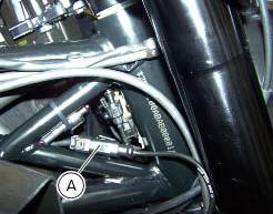
Disconnect the front abs sensor (2) connector (a) from the main electric wiring.
Open all the retainer clamps of the front abs sensor cable (2): refer to table of sect. 7 - 6, Flexible wiring/hoses positioning.

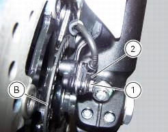
Loosen retaining screw (1) and remove the front abs sensor (2) with calibrated gasket (3).
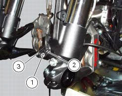
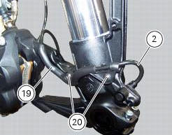
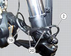
Undo the screws (20), remove the guide (19) and slide out the front abs sensor cable (2).
Before refitting, make sure that the contact parts between the front abs sensor (2) and its seat are not damaged and are perfectly clean.
Fit the new front abs sensor (2) in the relevant seat.
Insert the front abs sensor cable (2) in the guide (19) and fix it on the lh fork leg by starting the screws (20).
Tighten the screws (20).
Refit the front wheel as indicated in sect. 7 - 1, Refitting the front wheel.
Connect the connector (a) to the main wiring.
Restore all the retainer clamps of the front abs sensor cable (2): refer to table of sect. 7 - 6, Flexible wiring/hoses positioning.
Check the air gap between the front abs sensor (2) and the front phonic wheel (b) as indicated in sect. 7 - 7, Adjusting of the air-gap phonic wheel sensor.
Tighten the screw (1) to the torque of 10 nm +/- 10% (sect. 3 - 3, Frame torque settings).
 System components
Screw
Abs front speed sensor
Sealing washer
Hose grommet
Abs rear speed sensor
Abs control unit
Front pump - control unit pipe
Control unit - front callipers pipe
Rear pump - co ...
 Replacing the rear phonic wheel sensor
Disconnect the rear abs sensor (5) connector (c) from the main electric
wiring.
Open all the retainer clamps of the rear abs sensor cable (5): refer to table of
sect. 7 - 6, Flexible wiring ...
Other materials:
Adjusting the position of the gearchange and rear brake
pedals
The position of the gearchange and rear brake pedals in
relation to the footrests can be adjusted to suit the
requirements of the rider.
Adjust the pedals as follows:
Gear change pedal (fig. 97)
Hold the linkage (1) and slacken the lock nuts (2) and (3).
Note
Nut (2) has a left-hand thr ...
Engine
Twin cylinder, four-stroke, 90 "l" type, longitudinal, with
deep sump die-cast crankcase.
Bore, mm: 106
Stroke, mm:
67.9
Total displacement, cu. Cm:
1198
Compression ratio:
11.5±0.5:1
Max power at crankshaft (95/1/ec), kw/hp:
119 kw/162 hp at 9,500 rpm
Max torque at crankshaf ...
Refitting the front wheel
When all the necessary inspections have been completed, refit the wheel as
follows.
Fit the spacers (3) and (9) to the seal rings on the sides of the wheel hub.
Install the complete wheel between the fork legs.
Lubricate the shank and thread of the wheel axle (10).
Take the pin ...