
Ducati Diavel Owners Manual: Instrument panel on handlebar
- Lcd.
- Neutral light n (green). Illuminates when the gearbox is in neutral.
- High beam light
 (blue).
It turns on to indicate that the high beam lights are on.
- Engine oil pressure light

(red).
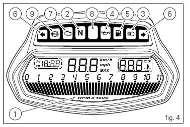
Illuminates when engine oil pressure is too low. It must turn on at key-on, but must turn off a few seconds after the engine has started.
It may come on briefly if the engine is very hot, but should go out again as engine speed increases.
 Important
If this light (4) stays on, stop the engine or it may suffer severe damage.
- Fuel warning light
 (amber
yellow).Comes on when fuel is low and there are about 4 litres of fuel left in the tank.
- Turn indicator lights

(green).Illuminates and flashes when the turn indicator is in operation.
- "Engine/vehicle diagnosis - eobd" light

(amber yellow).
It turns on in the case of "engine" and/or "vehicle" errors and in some cases will lock the engine.
- Limiter light "over rev"/ traction control light "dtc"
(red) (fig. 4):
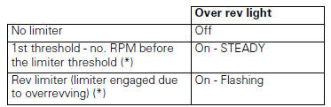
(*) Depending on the model, each calibration of the engine
control unit may have a different "setting" for the
thresholds that precede the rev limiter and the rev limiter
itself. 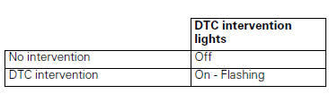
 Note
Note
If the over rev function light and the dtc intervention light should both come on at the same time, the instrument panel gives priority to the over rev function.
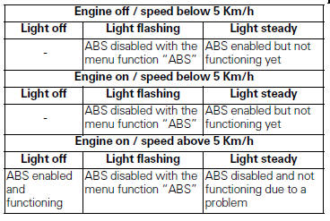
- Abs lights
 (amber yellow)
(fig. 4).This turns on to indicate that abs is disabled or not Functioning.
 Instrument panel (dashboard)
The vehicle is equipped with two instrument panels: an lcd
(1, fig. 3) Located on the handlebar containing the key
indications (speed, rpm, coolant temperature and clock) and
a tft colour display ( ...
 Lcd unit functions
Speedometer.
Gives road speed.
Rev counter.
Indicates engine revs per minute.
Clock.
Water temperature indicator.
Indicates engine coolant temperature.
Important
Stop riding i ...
Other materials:
Backlighting setting function for the dashboard on handlebar - dashboard 2
This function allows backlighting setting of the dashboard on handlebar.
To access the function it is necessary to view the ""setting" menu", using
buttons (1) "s" or (2) "t" select the "back
light" function and press the reset button (3) to enter the following page.
Use button (1) "s" or ( ...
Refitting the rear wheel
Lubricate the wheel shaft threaded end with prescribed grease.
Insert the wheel shaft by matching (a) with pins (b).
Install spacer (3) with the conical surface faced to the wheel conical
surface, washer (2), apply prescribed grease to nut
(1) and insert it by hand (1).
Tighten the ...
Refitting the timing gears
Before reassembling the removed parts, check timing gears (13) for wear.
Change, if necessary.
Important
The timing gears (13) must always be renewed as a pair.
Refitting is the reverse of removal.
Warning
When introducing the driven gear (b) check that the tongue (15) is
correctly fitted o ...