
Ducati Diavel Service Manual: Refitting the number plate holder
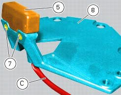
Place the number plate light (5), as indicated, on the number plate holder plate (8) and tighten the screws (7) to a torque of 2 nm +/- 10% (sect. 3 - 3, Frame torque settings).
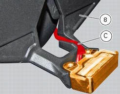
Thread the number plate light wiring (c) into the opening in the number plate holder plate as shown.
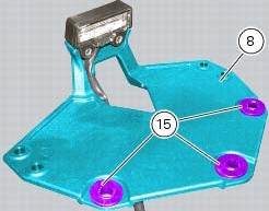
Fit the vibration dampers (15) in the corresponding holes of the number plate holder plate (8). Position the splashguard (16) on the number plate support subframe (9).
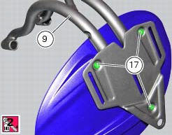
Apply prescribed threadlocker on the screw threads (17).
Fix the splashguard (16) by tightening the screws (17) to a torque of 5 nm +/- 10% (sect. 3 - 3, Frame torque settings).
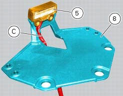
Position the number plate light wiring (c) into the seat in the number plate holder plate (8) as shown.
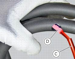
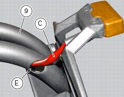
Insert the connector (d) of the number plate light wiring (c) into the hole (e) in the number plate support subframe (9), threading it out of the hole on the opposite side.
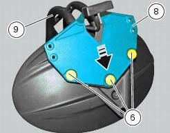
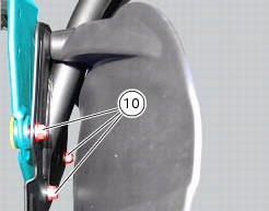
Fit the number plate holder plate (8) to the number plate support subframe (9), fitting the special screws (6) into the vibration dampers and starting the nuts (10) on the opposite side.
Note
Slide the plate (8) along the slots (g) in the subframe (9) until bringing it all the way towards the bottom side.
Tighten the special screws (6) to a torque of 5 nm +/- 10% (sect. 3 - 3, Frame torque settings), by holding the nuts (10) on the opposite side.
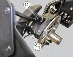
Reposition the assembly on the swingarm and tighten the screws (11) to a torque of 25 nm +/- 10% (sect. 3 - 3, Frame torque settings).
 Removal of the licence plate holder
Disconnect connector (5) of the number plate holder wiring from the main one.
Release the number plate holder light cable from the ties and the cable grommets
as indicated in sect- 7 - 6, fle ...
 Removal of the tail light
Disconnect the connectors (a) and (b) of the tail lights (1) and (13).
Loosen the screws (4) and slide the tail lights (1) and (13) to the rear side;
recover the four spacers (3) and the wash ...
Other materials:
Refitting the alternator-side crankcase cover
Before the assembly make sure that the water pump unit is fitted on the
generator cover (sect. 9 - 3.3, Refitting the
water pump).
If bearing (27) has been removed, lubricate its seat with specified grease to
fit it on the generator cover (13).
Fit bearing completely in its seat and orien ...
Overhaul of the cylinder barrel/piston components
Overhauling the cylinder
Check that the walls of the cylinder bore are perfectly smooth. Measure the
cylinder bore diameter at 50 mm from the top
face and determine the size class to which it belongs in accordance with the
values specified in sect. 3 -
1.1Cylinder/piston. Repeat measurement o ...
Routing of wiring on frame
The routing of the wiring has been optimised to ensure the minimum
obstruction.
Each section is designed to prevent interference with parts that might damage
wires or cause operating failures when
riding. The plates on the following pages show the origins ("0" points) for
correct re-routin ...