
Ducati Diavel Owners Manual: Lap activation/deactivation function (lap time)
This function activates and deactivates the lap function (lap time).
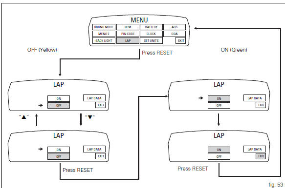
To access the function it is necessary to view the "setting" menu page 48, using
button (1, fig. 14) ?"
" or (2, fig. 14) ?" " select the "lap" function and
press the reset button
(12, fig. 12) To go to next page.
Function state is highlighted on the display (on in green or off in yellow); use
button (1, fig. 14) ?"
" or (2, fig. 14) ?" "
"
to shift the arrow on the left onto the new setting and
confirm by pressing the reset button (12, fig. 12).
To exit the setting function, press the reset button (12, fig.
12) Where "exit" is highlighted.
Storing the "off" condition disables the lap function.
Storing the "on" condition enables the lap function (see "lap registration" paragraph).
 Note
Note
When the "lap" function is active, the flash button (11, fig. 12) Takes on the dual function of high beam headlight "flash" and lap time start / stop.
 Digital rpm indication function
This function displays the number of rpms for improved
accuracy when setting idle rpm.
To access the function it is necessary to view the "setting" menu page 48, using
button (1, fig. ...
 Lap registration function
This function describes the "lap" time registration.
If the function is activated (see "lap activation/deactivation
description), the lap time can be registered as follows:
Pres ...
Other materials:
Default function (resetting ducati default parameters)
This function resets the parameters set by ducati for each riding style.
To access the function it is necessary to view the ""setting" menu", using
buttons (1) "s" or (2) "t" select the "riding
mode" function and press the reset button (3) to enter the following page.
Use button (1) "s" or ...
Trip 2 meter
This function shows the distance travelled since the trip
meter was last reset (in km or miles depending on the
specific application).
Holding the button (1, fig. 14) ?
pressed for 3 seconds
when this function is displayed resets the trip meter.
When the reading exceeds 9999.9, Distance t ...
Removal of the control unit
Loosen the screws (1) and remove the relay supporting bracket (2), disconnect
the connectors (3) and remove the control
unit (4) from the vehicle.
...