
Ducati Diavel Service Manual: Main bearings
The main bearings have are of the angular contact type with offset inner races so that the balls transmit loads from one groove to the other along straight lines at an angle to the axis of the bearing. The angle-contact ball bearings are designed for bearing combined loading (radial-axial loads).
Bearings of this type can bear thrust loads in one direction only. In fact, under the action of a radial load inside the bearing, an axial force is created that must be counterbalanced by an axial force acting in the opposite direction; that is Why these bearings are generally fitted back to back in pairs.
Note
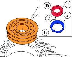
The main bearings supplied can be bearings with bushing (a) or flanged bearings (b) with the bushing integrated in the external ring of the bearing.
To renew the bearings proceed as follows:
- Heat the crankcase in an oven to 100 C;
- Remove the bearing using a drift and hammer;
- Install the new bearing (while the crankcase is still hot) keeping it perfectly square in its seat using a tubular drift that only bears on the outer ring of the bearing;
- Allow the parts to cool and check that the bearing is securely seated in the crankcase half.
Bearings with bushing
Important
On worn engines, the bearing holder may no longer be a tight fit in the crankcase half.
After having removed the bushing, check that the interference fit between the crankcase and the bushing, with bearing fitted, is no less than 0.03 Mm, otherwise, replace the crankcase halves.
Note
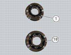
Fit the bearings (1) and (18) orienting them so that the side with the "letter" (c) is facing the bushings (2) and (17).
Flanged bearings
Important
On badly worn engines, bearing outer rings may have developed clearance in the crankcase halves - normally, bearing outer rings are interference-fit in the casing.
Check that the interference fit between the crankcase and the bearings (1) and (18) installed, is not less than 0.03 Mm, otherwise, replace the crankcase halves.
Important
After installing new main bearings, shim the crankshaft as described in the paragraph "shimming the shafts" and "reassembly of the crankcase halves" of this section.
 Overhaul of the crankcase halves
Carefully examine the engine crankcase halves.
Check that the surfaces of the crankcase halves are perfectly flat using a
reference surface.
Check that the bearings (1) and (18), and the bushing ...
 Reassembly of the crankcase halves
The crankcase halves must be in good condition and perfectly clean. The
mating surfaces must be perfectly flat and free
from burrs.
Overhauling the alternator-side crankcase half
The following pa ...
Other materials:
Reassembly of the oil pump
Check that the circlip (3) and tongue (13) are present on the pump.
Fit the pump drive gear (12) on to the oil pump and secure it by installing the
circlip (6) in its groove.
Insert the by-pass valve pump (17), the spring (16) and screw the plug (14).
Tighten the plug (14) to a torque of ...
Recovery procedure with no key
When the dashboard is on and the key has been recognised, the hands free
attempts to detect the key every 60 seconds.
If the engine is off and the on/off switch on the handlebar is turned to "run
off", if no key is detected within 10 seconds,
the dashboard switches off automatically.
If t ...
Refitting the external components
Fit the cap (39) on spring (38) until it engages.
Mount ball (40), spring (38) with cap (39), washer (37) and screw (36) on the
chain side half-casing by starting the
screw into hole (f).
Note
The spring (38), with cap (39), must be oriented as shown.
Tighten the screw fully home to a torqu ...