
Ducati Diavel Service Manual: Refitting the gearchange mechanism
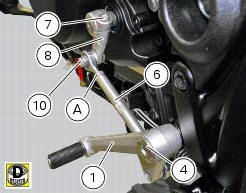
Make sure that the gearchange linkage assembly (6) is installed with the ball joint with a left-hand thread (a) facing the lever (8).
Apply the recommended grease to the non-threaded surface of the pin (4).
Fit the first o-ring (5) in the pin (4).
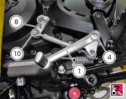
Start the pin (4) in the gearchange lever (1). Smear recommended grease on the second o-ring (5). Insert the second o Ring (5) and the washer (9).
Apply the recommended threadlocker to the threaded side of the pin (4). Fit the gearchange lever (1) on the footrest bracket and tighten the pin (4) to a torque of 23 nm +/- 10% (sect. 3 - 3, Frame torque settings).
Fit the lever (8) on the gearchange control assembly, and start the screw (10).
Tighten the screw (10) to the torque of 10 nm +/- 10% (sect. 3 - 3, Frame torque settings).
Fit the gear control unit inserting the lever (8) on the gear control pin, apply threadlocker on the screw (7) and insert it on the lever (8).
Tighten the screw (7) to a torque of 10 nm +/- 10% (sect. 3 - 3, Frame torque settings).
 Disassembly of the gearchange mechanism
Refer to the exploded view at the beginning of this section for indications
on disassembly and renewal of gearchange
components.
If the bushing (2) inside the pedal (1) needs replacing, grease t ...
 Fork
Fork
...
Other materials:
Abs disabling function
This function disables or enables the abs.
To access the function it is necessary to view the "setting" menu page 48, using
button (1, fig. 14) ?"
" or (2, fig. 14) ?"" select the "abs" function and
press the reset button
(12, fig. 12) To go to next ...
Running-in recommendations
Maximum rpm (fig. 114)
Rotation speed for running-in period and during standard use
(rpm)
Up to 1000 km;
From 1000 to 2500 km.
Up to 1000 km
During the first 1000 km, keep an eye on the rev counter.
It should never exceed
5500÷6000 rpm.
During the first hours of riding, it ...
Component assembling position
The throttle valve position sensor is integrated in the throttle valve
actuator motor.
Location of electric connection for throttle valve actuator motor - tps
(throttle valve position sensor).
Connection wiring diagram
Ccm engine control connection, s throttle valve position senso ...