
Ducati Diavel Service Manual: Refitting the flywheel-alternator assembly
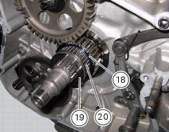
Fit the roller cage unit (20) with washer (18) and internal ring (19), applying prescribed grease on the washer (18).
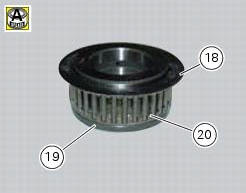
Install the roller cage assembly (20) with the washer (18) and inner race (19).
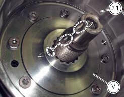
Install the flywheel assembly (v) with the gear (21), aligning the notches as shown in the photo.
Fit the washer (16) on the end of the crankshaft.
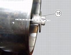
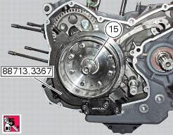
Apply the recommended threadlocker to the thread on the end of the crankshaft and the nut (15).
Start the nut (15) on the crankshaft.
Lock the flywheel rotation by means of tool number 88713.3367 And tighten the nut (15) to a torque of 330 nm (min.
313 Nm - max. 346 Nm) (sect. 3 - 3, Engine torque settings).
 Overhaul of the flywheel-alternator assembly
Examine the inner part of alternator rotor (24) for signs of damage. Check
that the starter clutch is working properly and
that the needle races do not show signs of wear or damage of any kind. If ...
 Refitting the alternator-side crankcase cover
Before the assembly make sure that the water pump unit is fitted on the
generator cover (sect. 9 - 3.3, Refitting the
water pump).
If bearing (27) has been removed, lubricate its seat with speci ...
Other materials:
Removal of the cooling system hoses and unions
Loosen the clips (21) that secure the radiator/thermostat sleeve (40) and the
radiator/plug sleeve (24) to the water
radiators.
Loosen clips (25) and (43) that secure the breather pipe (26) to the
radiator/plug sleeve (24) and to the left radiator.
Loosen the clips (34) securi ...
Start procedure with pin code (no keys)
The motorcycle may be started without keys with a special procedure using the
dashboard and the switches on the
handlebar.
Note
This procedure is only possible if the pin code has been enabled
previously. For security reasons, the pin code is disabled
by default when the vehicle leaves the f ...
Overhauling the front forks
Note
It is advisable to loosen the top cap (14) when the fork is still fitted
to the motorcycle.
Note
The specific tools for the revision of the fork, are described in sect. 3
- 4, Specific tools for the frame.
Loosen the spring preload adjuster before unscrewing the plug (14).
Unscrew th ...