
Ducati Diavel Service Manual: Separation of the crankcase halves
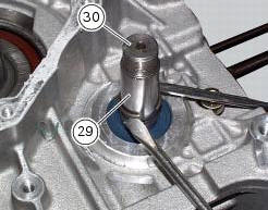
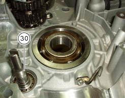
Use two screwdrivers to remove the circlip (29) from the timing belt driveshaft shaft (30) on the clutch-side crankcase half.
Note
Take care to avoid scoring the surface of the shaft while removing the circlip.
Unscrew the crankcase half screws on the chain side.
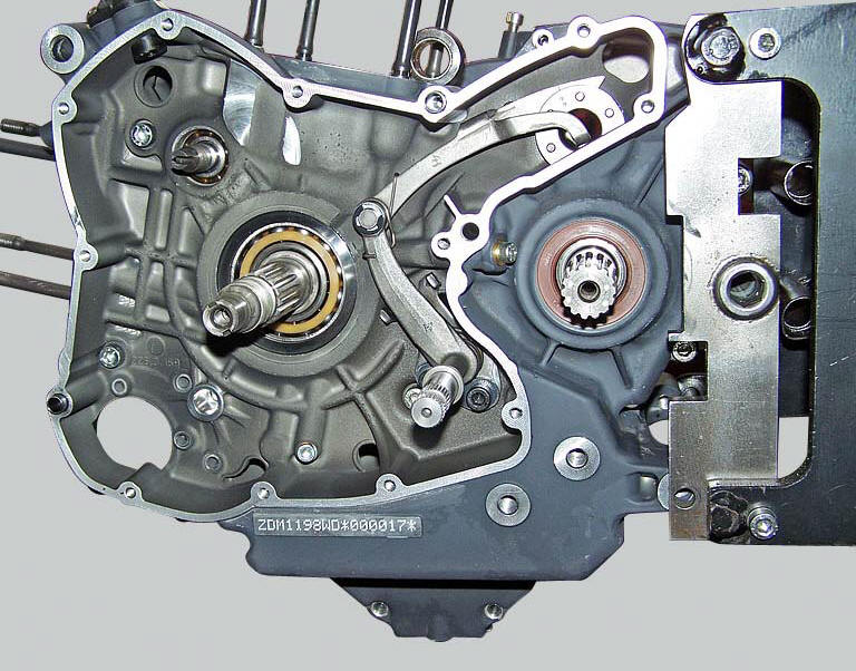
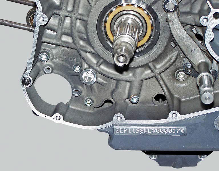
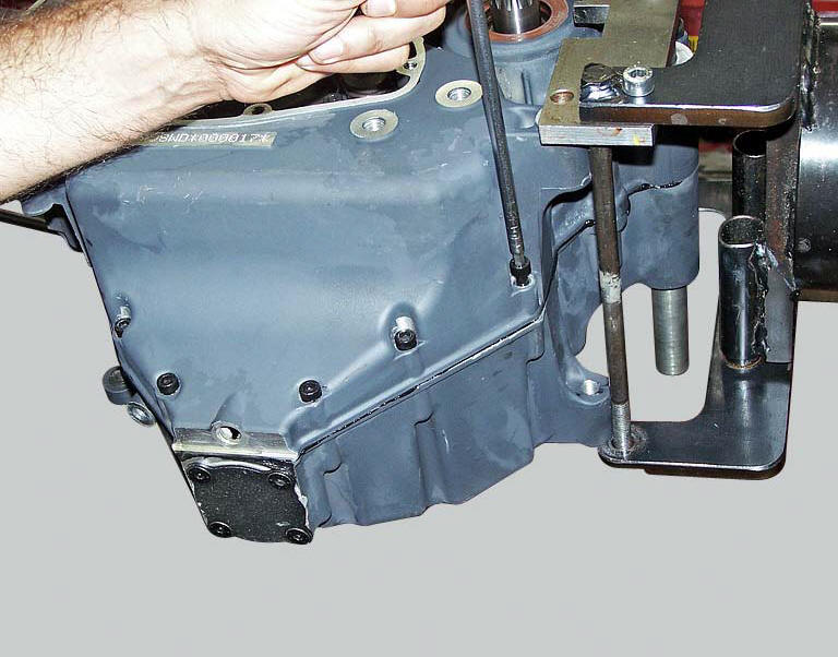
Unscrew the two screws (12) on the clutch side near the vertical cylinder.
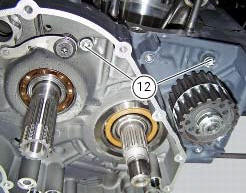
Reuse the alternator cover or a service cover with puller 88713.1749 Fitted. Secure cover to crankcase half with some of the original screws and begin separation by turning the central pin of the tool.
Tap the end of the gearbox secondary shaft with a plastic mallet to separate the crankcase halves.
Note
Take care not to lose the shims on the shafts and on the selector drum.
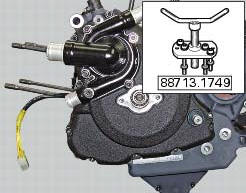
Remove gearbox shafts and gearbox selector drum from the crankcase halves (sect. 9 - 7.2, Removal of the gearbox assembly.
Drive out the crankshaft (l) using a plastic mallet, taking care not to lose the shims.
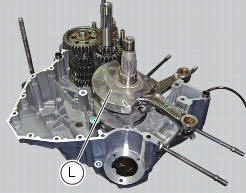
Remove the timing belt driveshaft (30).
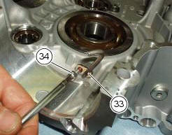
Remove the screws (34), remove the pipes (33) and collect the o-rings (32).
 Crankcase halves
Bearing
Bearing holder bushing
Alternator-side crankcase half
Bearing
Circlip
Washer
Bearing
Sealing ring
Bearing
Retaining plate
Screw
Screw
Clutch-side crankcase half
...
 Overhaul of the crankcase halves
Carefully examine the engine crankcase halves.
Check that the surfaces of the crankcase halves are perfectly flat using a
reference surface.
Check that the bearings (1) and (18), and the bushing ...
Other materials:
Units of measurement modification function
This function allows you to change the units of measurement
of the displayed values.
To access the function it is necessary to view the "setting" menu page 48, using
button (1, fig. 14) ?"" or (2, fig.
14) ?" " select the "set units" function
and pre ...
Checking the frame
Check the dimensions of the frame against the dimensions shown here to
determine whether it needs to be realigned or
renewed.
Important
Damaged frames must be changed, not repaired. Any work carried out on the
frame can give rise to potential danger,
infringing the requirements of ec directi ...
Checking valve clearances
To check the valves clearance, it is necessary to have access to the cylinder
head covers and then remove the
components listed below.
Unscrew the two fixing screws (1) of the cover (2) according to the
crankshaft.
Fit the tool handgrip 88713.0123 In the holes of the generator cover t ...