
Ducati Diavel Service Manual: Refitting the shock absorber support
If you had removed them, apply recommended grease on the threads of the adjusters (4) and the ring nuts (3) having care not to have grease on the surface (c) of the adjusters.
Tighten the adjusters on the ring nut side opposite to that featuring flats until bringing the surfaces as close as possible as shown.
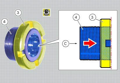
Start (form the external side of the support) the adjusters (4) in the bushes on the support.
Tighten the adjusters (4) to a torque of 0.6 Nm +/- 10% (sect. 3 - 3, Frame torque settings).
Note
If at the specified torque the adjusters should not tighten properly, maybe the support or the adjusters could be nonconforming.
Loosen the adjusters (4) until bringing the surfaces as close as possible to the internal profiles of the support bushes.
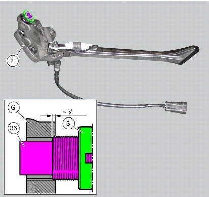
If you had removed the adjuster (36), apply recommended grease on the threads of the adjusters and the ring nut (3) having care not to have grease on the surface (c) of the adjuster.
Tighten the adjuster on the ring nut side opposite to that featuring flats until bringing the surfaces as close as possible as shown.
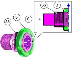
Start the adjuster (36) and tighten it manually (y is equal to about 2 threads) on the external side of the plate of the side stand assembly (g).
Note
During this operation, be sure to keep ring nut (3) in position, i.E. Flush with the external surface of the clearance adjuster (36).
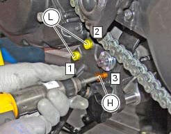
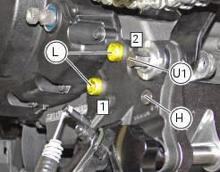
Apply the recommended grease to the threads and undersides of the heads of the screws (l) and (h).
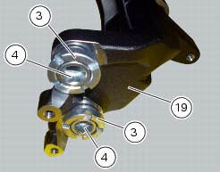
Position the shock absorber support (19) and the side stand assembly (g) on the left-hand side of the engine and start the screws (l) and (h).
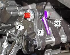
Insert a suitable centring pin (u1) on the adjuster (36), making sure that the pin hexagon fits properly into the hexagon socket of the adjuster.
Insert the bush (6) to keep the components in place.
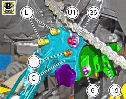
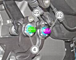
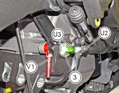
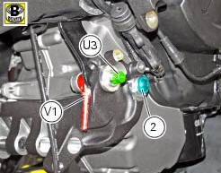
On the right side, insert a suitable centring pin (u2) on the front adjuster (4) and a suitable centring pin (u3) on the rear adjuster (4), making sure that the pin hexagons fit properly into the hexagon sockets of the adjusters.
Tighten the screws (l) and (h) to a torque of 7 nm +/- 10% (sect. 3 - 3, Frame torque settings), by following the sequence 1-2 -3.
On the right side, extract the front centring pin (u2).
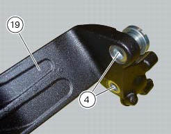
Tighten the front adjuster (4) to a torque of 0.6 Nm +/- 10% (sect. 3 - 3, Frame torque settings) and then make sure it is fully home on the crankcase.
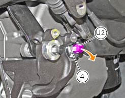
Again on the right side, refit the front centring pin (u2) making sure that the pin hexagon fits properly into the hexagon socket of the adjuster.
Extract the rear centring pin (u3).
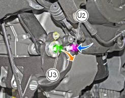
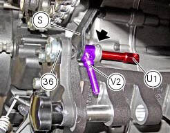
On the right side, insert the rear centring pin (u3) from the internal side of the crankcase, placing a suitable spacer (v1) between crankcase and rh rear suspension support bracket (s).
Tighten the rear adjuster (4) to a torque of 0.6 Nm +/- 10% (sect. 3 - 3, Frame torque settings) and then make sure it is fully home on the bracket (s).
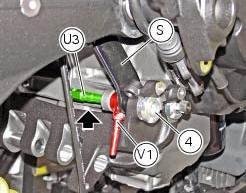
On the right side, extract the rear centring pin (u3) from the internal side and refit it on the outside, while keeping the right spacer (v1) in place.
Warning
Make sure that the pin hexagon fits properly into the hexagon socket of the adjuster.
Locate service tool no. 88713.3166 On the front ring nut (3) and fit the torque wrench to the tool. Tighten the front ring nut (3) of the front adjuster to a torque of 100 nm +/- 5% (sect. 3 - 3, Frame torque settings) while holding the adjuster using centring pin (u2).
Then locate service tool no. 88713.3166 On the rear ring nut (3) and fit the torque wrench to the tool. Tighten the rear ring nut (3) of the rear adjuster to a torque of 100 nm +/- 5% (sect. 3 - 3, Frame torque settings) while holding the adjuster using centring pin (u3).
Apply the recommended grease to the thread and the underside of the front screw (2).
On the right side, extract the front centring pin and start the front screw (2) at the same position, tightening it manually until fully home.
Extract the rear centring pin (u3) and the right spacer (v1).
Apply the recommended grease to the thread and the underside of the rear screw (2).
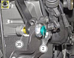
Start the rear screw (2) and, on the opposite side, tighten the nut (35).
Tighten the front screw (2) to a torque of 45 nm +/- 10% (sect. 3 - 3, Frame torque settings).
Tighten the rear screw (2) to a torque of 45 nm +/- 10% (sect. 3- 3, Frame torque settings) while holding the nut (35).
On the left side, tighten the screws (l) to a torque of 45 nm +/- 10% (sect. 3 - 3, Frame torque settings), by following the sequence 1-2.
Then tighten the screw (h) securing the side stand plate to the shock absorber support to a torque of 45 nm +/- 10% (sect. 3 - 3, Frame torque settings).
Extract the centring pin (u1).
Insert the centring pin (u1) from the internal side of the crankcase, placing a suitable spacer (v2) between crankcase and rear left suspension support bracket (s).
On the left side, tighten the adjuster (36) to a torque of 0.6 Nm +/- 10% (sect. 3 - 3, Frame torque settings) and then make sure it is fully home on the rear left suspension support bracket (s).
Extract the centring pin (u1) from the internal side and refit it on the outside, while keeping the left spacer (v2) in place.
Warning
Make sure that the pin hexagon fits properly into the hexagon socket of the adjuster.
Locate service tool no. 88713.3166 On the ring nut (3) and fit the torque wrench to the tool.
Tighten the ring nut (3) to a torque of 100 nm +/- 5% (sect. 3 - 3, Frame torque settings) while holding the adjuster using the centring pin (u1) located inside the adjuster.
Extract the centring pin (u1) and the spacer (v2).
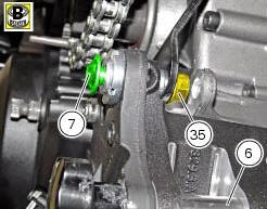
Apply the recommended grease to the thread and the underside of the left-side screw (7).
On the left side, start the screw (7) and, on the opposite side, tighten the nut (35).
Tighten screw (7) to a torque of 45 nm +/- 10% (sect. 3 - 3, Frame torque settings) while holding the nut (35).
Extract the bush (6).
 Removal of the shock absorber support
Remove the rear brake master cylinder (sect. 7 - 4, Removing of the rear
brake control).
Remove the rear shock absorber (see removal of the rear shock absorber of this
section).
Loosen the s ...
 Swingarm
Swingarm pivot
Washer
Special screw
Bush
Sealing ring
Roller bearing
Special screw
Rear swingarm
Spacer
Bearing
Spacer
Spacer
Hose clip
Pin
Chain slider (lower)
Wa ...
Other materials:
Checking the coolant level
To the specified intervals in the "scheduled maintenance chart" (sect. 4 - 2)
Check the coolant level contained in
the expansion reservoir, on the right side of the vehicle.
The coolant level must be between the max. And min marks on the tank.
If the level is low, top up with the recommende ...
Replacing the tank flange and fuel sensor
Loosen the screws (19) securing the fuel tank flange (20).
Remove the flange (20) from the tank (20).
Recover the seal (21).
Undo and remove the two fixing screws (g) and move the protection (f).
Before reassembly, carefully remove any deposits or scale from all parts.
Note
The flang ...
High engine coolant temperature
The activation of this (amber yellow) "warning" indicates
that the engine coolant temperature is high.
It is activated when the temperature reaches 121C (250f).
Note
In this case, ducati recommends stopping and shutting
off the engine immediately; make sure that the fans are
workin ...