
Ducati Diavel Service Manual: Refitting the handlebar
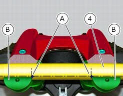
Position the handlebar (4) so that the external lower corner of the marks (a) on the handlebar matches the upper internal corner of the lower u-bolts (b) as shown.
Apply the recommended grease to the threads and undersides of the heads of the screws (3).
Important
Position the upper u-bolt (1) as shown.
Refit the upper clamp (1) and insert the screws (3).
Tighten the screws (3) to a torque of 25 nm +/-5% (sect. 3 - 3, Frame torque settings), applying the sequence 1-2-3-4-3, as indicated in the figure.
Adjusting the throttle cable
To operate on the set screws of the throttle grip cables, consult sect. 4 - 3, Adjusting the throttle cable.
 Removal of the handlebar
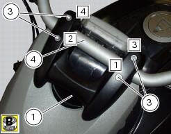
Unscrew and remove the screws (3) securing the upper clamp (1).
Remove the upper clamp (1).
Remove the handlebar (4) from its seat on the steering head.
To remove the grips (5), refer ...
 Removal of the throttle twistgrip
Peel back the rubber sleeve (a) protecting the throttle control cables.
Undo the screws (b) of the throttle grip (6) and open the command.
Disconnect the throttle grip cables (10) by unhooking ...
Other materials:
Location of elements on motorcycle
(A) injection relay; (b) etv relay (throttle valve operating engine); (c)
radiator fan relay; (d) hands free relay.
(E) ecu; (g) bbs (black box system or central electronics); (f) abs hydraulic
unit with integrated control unit.
Fuses located at the rear left of the vehicle.
...
Turn indicators not working
Fault codes
Dds: no fault code displayed.
Dashboard: no fault code displayed.
Wiring diagram
Db dashboard connection, bbs bbs unit connection, s turn indicator button, f1
front left turn indicator, f2 front right
turn indicator, f3 rear left turn indicator, f4 rear right turn indicator. ...
High beam flash not working - start/stop lap function not working
Fault codes
Dds: no fault code displayed.
Dashboard: no fault code displayed.
Wiring diagram
Db dashboard connection, s high beam flash button. 7 Orange - o, 1
red/blue - r/b.
Location of connections and components
Location of left hand handlebar switchgear set connection.
Pin ...