
Ducati Diavel Service Manual: Refitting the oil pump
If removed, apply specific threadlocker on the bushing (7) outer thread, and screw it in the crankcase half, observing the height.
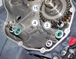
Position the reference bushings (15) and the oil sealing o-rings (2) and (4) according to the crankcase lubrication channels.
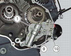
Position the oil pump on the crankcase and tighten screws (9) to a torque of 26 nm (min. 23 Nm - max. 29 Nm) and the screw (10) to a torque of 10 nm (min. 9 Nm - max. 11 Nm) (sect. 3 - 3, Engine torque settings).
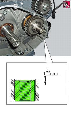
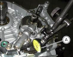
Check the gear clearance with the driving pinion by fixing a dial gauge (a), equipped with the appropriate traces, to the crankcase half.
Position the dial gauge stylus on one tooth of oil pump gear and set the gauge to zero in this position.
Move the gear slightly to measure the backlash; take four readings in diametrically opposed positions of the gear.
The clearance should be 0.10 Mm.
 Reassembly of the oil pump
Check that the circlip (3) and tongue (13) are present on the pump.
Fit the pump drive gear (12) on to the oil pump and secure it by installing the
circlip (6) in its groove.
Insert the by-p ...
 Oil cooler
Oil cooler
Vibration damper mount
Spacer
Screw
Nipple
Aluminium gasket
Oil delivery hose
Screw
Plate
Bracket
Screw
Engine oil pressure sensor
Sealing washer
Heat guard ...
Other materials:
Removal of the handlebar
Unscrew and remove the screws (3) securing the upper clamp (1).
Remove the upper clamp (1).
Remove the handlebar (4) from its seat on the steering head.
To remove the grips (5), refer to the exploded view at the beginning of this
chapter.
...
Overhauling the rear wheel
Inspect the condition of the rear wheel.
As the wheel rim has no bearings, it should be supported using the service tool
code 88713.2951.
Note
This service tool can also be used to install the wheel on a balancing
machine.
Overhauling the wheel
Inspect the wheel as described below.
...
Front wheel
Nut
Washer
Left spacer
Sealing ring
Bearing
Front wheel rim
Inner spacer
Screw
Right spacer
Front wheel shaft
Valve
Spare parts catalogue
Diavel abs front and rear wheels
Diavel carbon
abs
front and rear wheels
Important
Bold reference numbers in this section iden ...