
Ducati Diavel Service Manual: Removal of the oil pump
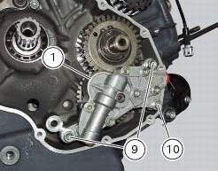
Undo and remove the screws (9) and (10) securing the pump assembly.
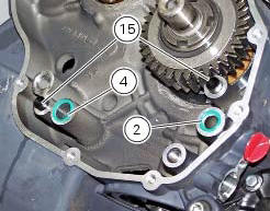
Remove the oil pump assembly (1) and extract the o-rings (2) and (4) from the crankcase half together with two locating bushes (15).
 Oil pump
Complete oil pump assembly
O-ring
Circlip
O-ring
Pump body
Circlip
Reducer bush
Spring washer
Screw
Screw
Spring washer
Pump drive gear
Key
By-pass plug
Locating bus ...
 Disassembly of the oil pump
Hold the oil pump (1) in a vice taking care not to damage the drive gear
(12).
Warning
Make sure that vice jaws are faced with soft material.
Remove the plug (14) and extract the spring (16) ...
Other materials:
Operations to be carried out by the dealer
List of operations to be performed at 1000 km
Reading of the error memory with dds on the engine control units,
vehicle and abs
Change the engine oil
Change the engine oil filter
Check the indicators and lighting
Check the safety devices (side ...
Removing the front footrest brackets
Note
The assembly of the front footrests is described only for the right one
(2) but it is the same also for the left one.
Place the spring (4) bringing the end (a) onto the footrest (2).
Place the footrest (2) in the correct position, by inserting the end (c) of the
spring (4) in the hole ...
Checking drive chain tension
Important
Have chain tension adjusted by a ducati dealer or
authorised service centre.
Make the rear wheel turn until you find the position where
chain is tightest.
Set the vehicle on the side stand. Push down the chain at the
point of measurement and release.
Measure the distance betwee ...