
Ducati Diavel Service Manual: Reassembly of the tool tray
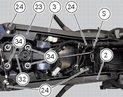
Place the tool tray unit (23) on the lateral brackets (2) and (3) by tightening the screws (24) to 14 nm +/- 5% (sect. 3-3, Frame torque settings).
If the handle guide (32) has been previously removed, position it on the tray (23) and tighten the screws (34) to 20 nm +/- 5% (sect. 3-3, Frame torque settings).
Reposition the wiring branch in the seat (s) in the tray (23).
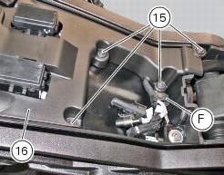
Place the gloves compartment cover (16) on gloves compartment (23), inserting wiring (c) into the suitable recess in the cover (16).
Warning
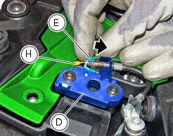
While positioning the cover (16) on the compartment (23), push bracket (e) of the lock latch (d) in the direction shown by the arrow, to prevent the lock wire terminal (h) from being squeezed under the cover.
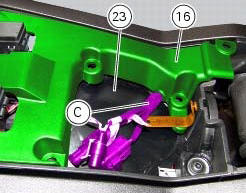
Check the presence of the clip (f) on the cover (16).
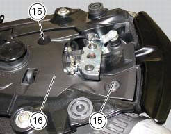
Fix the cover (16) by tightening the screws (15) to a torque of 4 nm +/- 10% (sect. 3 -3, Frame torque settings).
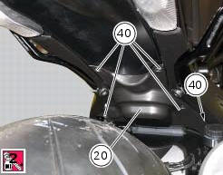
Apply the recommended threadlocker to the screws (40).
Reposition the splashguard (20) and tighten the screws (40) to a torque of 4 nm +/- 10% (sect. 3 -3, Frame torque settings).
 Reassembling the frame and the lateral footrests
Apply the recommended grease to the thread of the pins (9) and of the nuts
(8).
Place the frame (1) and the brackets (2) and (3) on the engine block. Start the
pins (9) by holding the nuts (8) ...
 Tail light - number plate holder
Rh tail light
Vibration damper mount
Spacer
Screw
Number plate light
Screw
Screw
Plate
Number plate holder
Nut
Screw
Rear chain guard
Lh tail light
Spring washer
Vib ...
Other materials:
Wiring diagram of the hands free system
The diagram illustrates the inputs, outputs and communication lines used by
the hands free system.
1I - on/off button placed on the hands free system (located below the plastic
cover)
2I - on/off button placed on the bike handlebar rh side
3I - steering position micro-switch
4I - steerin ...
Abs system operating information
The response of the system is based on the analysis of the speed signals for
front and rear wheels; the system is
automatically deactivated if either of these signals is missing.
Note
In the event of the abs control unit detecting a fault in the abs
electronic management system, it activates ...
Disassembly of rear shock absorber - rocker arm - linkage assembly
Undo the screw (15) and remove the rear shock absorber (11) from the rocker
arm (18).
Undo
Undo the screw (14) and the nut (21) and remove the linkages (10) and (12)
from the rocker arm (18).
The rocker arm movement is obtained by needle roller bearings (9) rotating on
a spacer (1 ...