
Ducati Diavel Service Manual: Refitting the tail light
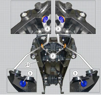
Fit the spacers with collar (3) into the rear vibration dampers (2) located on the gloves compartment (23).
Note
Two spacers (3) must be inserted inside and outside on the right side and two spacers (3) must be inserted inside and outside on the left side.
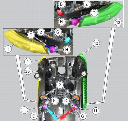
Insert the split vibration damper (h) on the wiring (g) of the left optical unit (13) and the split vibration damper (h) on the wiring (c) of the right optical unit (1).
Note
The usa version uses red optical units (13) and (1).
Fit the left optical unit (13) and the right optical unit (1) on the compartment (23), inserting their pins (d) and (e) into the vibration dampers (2).
Fit the split vibration dampers (h) into the corresponding holes of the compartment (23).
Fit the washers (14) on the screws (4).
Fix the optical units (13) and (1) to the compartment (23) starting the screws (14).
Note
The screws (14) must be inserted into the internal spacers (3) fitted previously.
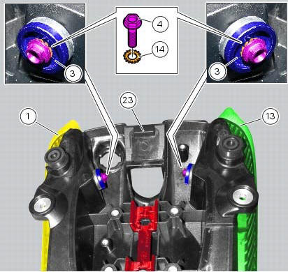
Tighten the screws (4) to a torque of 6 nm +/- 10% (sect. 3 - 3, Frame torque settings).
 Removal of the tail light
Disconnect the connectors (a) and (b) of the tail lights (1) and (13).
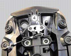
Loosen the screws (4) and slide the tail lights (1) and (13) to the rear side;
recover the four spacers (3) and the wash ...

Other materials:
Steering head: steering
Screw
Steering head
Screw
Lower rh u-bolt
Lower lh u-bolt
Bearing
Screw
Sealing ring
Washer
Spacer
Washer
Nut
Washer
Screw
Bottom yoke
Dowel
Nut
Screw
Special screw
Clip nut
Left-hand support
Front splashguard
Right-hand support
Front support
S ...
Guided diagnosis
Note
The on-screen icons used during this procedure are explained in a table at
the end of this section.
The dds diagnosis instrument guides the operator step-by-step through the
various diagnostic procedures,
providing descriptions and documentation for motorcycle components, wiring
diagra ...
Default function (resetting ducati default parameters)
This function resets the parameters set by ducati for each
riding style.
To access the function it is necessary to view the "setting" menu page 48, using
button (1, fig. 14) ?"
" or (2, fig. 14) ?" " select the "riding mode"
function and press the
r ...