
Ducati Diavel Service Manual: Removal of the cylinder/piston assembly
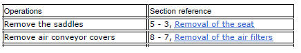
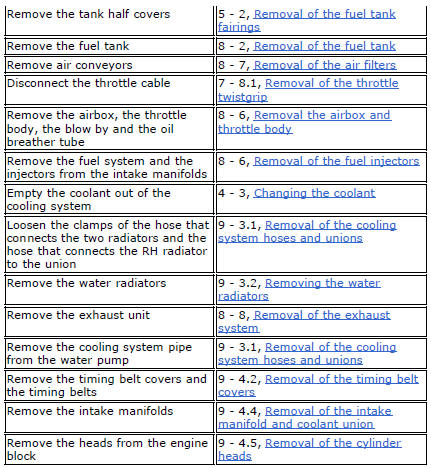
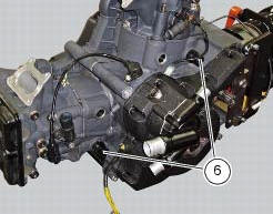
Loosen the clamps (7) and remove the hoses (8) and (9) from the cylinder barrels (10) and from the alternator-side crankcase cover.
If damaged, unscrew the unions (6).
Note
The following procedure is described with the engine removed from the frame and the cylinder head removed from the engine (sect. 9 - 4.5, Removal of the cylinder heads).
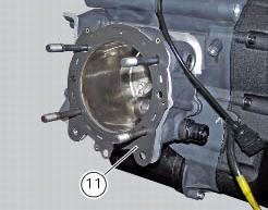
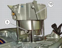
Remove the gasket (11) from the horizontal thermal unit.
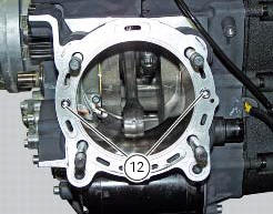
Remove the bushes (12).
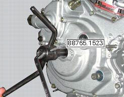
Use the tool 88765.1523 To bring the piston of the horizontal cylinder near the tdc.
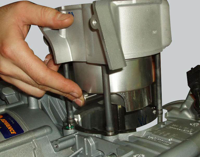
Carefully lift the cylinder barrel (10) off the crankcase, keeping it vertical.
If necessary, rock the cylinder slightly using both hands or tap its base gently with a rubber mallet. Continue to lift the cylinder until you can access the gudgeon pin (3).
Note
For better sealing the piston ring gaps should be positioned at 180 intervals.
Since insertion of piston in the barrel is a difficult operation to perform at the time of reassembly, remove the piston together with the barrel as described below.
Stuff the crankcase opening with a rag or soft paper to prevent foreign material from falling in.
Remove the circlip (2) from the gudgeon pin (3) on the clutch side.
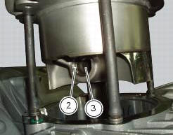
Working from the opposite side, drive out the gudgeon pin sufficiently to release the connecting rod.
Lift the barrel-piston assembly clear of the crankcase studs. If work is to be carried out on the piston, carefully withdraw it from the cylinder.
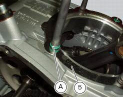
Remove the four o-rings (a) located on the crankcase studs between the barrel and the base gasket (5).
To remove the vertical barrel-piston assembly, bring the vertical piston to tdc and proceed as for removal of the horizontal cylinder barrel.
Important
Mark the pistons to show from which cylinder they were removed: v= vertical - h= horizontal.
 Cylinder/piston assemblies
Piston
Gudgeon pin circlip
Gudgeon pin
Set of piston rings
Cylinder-crankcase gasket
Water pump outlet union
Hose clip
Horizontal cylinder coolant inlet hose
Vertical cylinder c ...
 Overhaul of the cylinder barrel/piston components
Overhauling the cylinder
Check that the walls of the cylinder bore are perfectly smooth. Measure the
cylinder bore diameter at 50 mm from the top
face and determine the size class to which it belo ...
Other materials:
Footrest brackets
Rubber footrest
Right front footrest
Pin
Spring
Circlip
Right footrest bracket
Screw
Washer
O-ring
Bush
Rubber pad
Right rear footrest
Pin
Ball
Spring
Plate
Screw
Vibration damper mount
Special screw
Front lh footrest
Left footrest bracket
Left rear f ...
Steering lock on indication
This function informs that the steering lock was turned on.
The steering lock can be turned on during the first 60
seconds after turning off the vehicle by pressing down on the
"run" button.
If the steering lock was enabled correctly, the instrument
panel will show the indication ...
Starter motor
Power:
0.7 Kw/12 v
Direction of rotation:
counter clockwise viewed from power take-off side.
The starter motor is highly compact and reliable and therefore rarely gives
any type of problem. In case of troubles,
ensure that the starter motor cable terminal is properly tightened under the n ...