
Ducati Diavel Service Manual: Removal of the engine
In order to remove engine you must first remove a series of other components from the motorcycle.
Most of these removal procedures are described in the relative sections of this manual.
The following flow chart illustrates the logical sequence in which the parts are to be removed from the motorcycle and a reference to the section where the removal procedure is described.
This section describes only the operations to be carried out after having removed all the parts listed in the flow chart.
Place a stand beneath the engine to support it during removal from the frame.
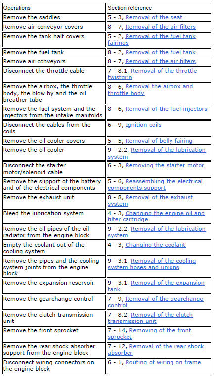
Loosen the nuts (3) on the right side of the frame, in correspondence to the engine upper supporting screws (1) and (4).
Block the special screw (6) of the swingarm shaft on the left side of the frame and at the same time undo the other special screw (6) on the right side.
Using the drift 88713.1074, Fully extract the swingarm shaft: from the lh side and recover the washer (7).
In this way the swingarm is not fixed to the engine any more, leave it connected to the frame.
Remove the upper supporting screws (1) and (4).
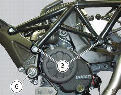
Withdraw the complete engine assembly from the frame by lowering it and pushing it forwards.
 Removal-refitting of the engine assembly
Screw
Special screw
Nut
Screw
Swingarm pivot
Special screw
Washer
Spare parts catalogue
Diavel abs frame
Diavel abs swingarm
Diavel carbon
abs
frame
Diavel carbon
abs
swi ...
 Refitting the engine
Refitting is the reverse of removal.
Important
Apply recommended grease and tighten the special screws (6) to a torque of
60 nm +/- 5% (sect. 3 - 3, Frame torque
settings).
Tighten the nuts (3) ...
Other materials:
Rear brake
Rear speed sensor (abs)
Screw
Washer
Spring
Brake switch (rear)
Brake lever (rear)
Rear pump - control unit pipe
Sealing washer
Pin
Bush
O-ring
Screw
screw
Rear brake disc
Rear brake calliper
Rear brake master cylinder
Hose clip
Pushrod
Screw
Rubber pad
...
Lcd unit functions
Speedometer.
Gives road speed.
Rev counter.
Indicates engine revs per minute.
Clock.
Water temperature indicator.
Indicates engine coolant temperature.
Important
Stop riding if the temperature reaches the maximum
value, otherwise the engine might be damaged.
...
Refitting the rear footrests
Note
The refitting of the rear footrests is described for the right side but it
is the same for both.
If previously removed, refit the rubber footrest (11) on the rear rh footrest
(6), by pushing it until pad (b) engages in the
other side.
Note
The rubber footrest (11) side featuring the le ...