
Ducati Diavel Service Manual: Refitting the front forks
Refit the fork legs, positioning them at the height shown in the figure relative to the upper surface of the bottom yoke.
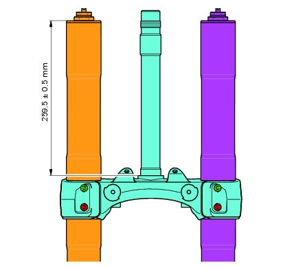
Warning
The difference in height between the two fork legs must be no greater than 0.1 Mm.
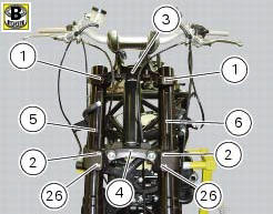
Position the fork legs (5) and (6) on the yoke base (4) and on the steering head (3).
Lock the fork legs by tightening the screws (1) to the torque of 20 nm +/- 5%, the screws (2) to the torque of 22 nm +/- 5%, and the screws (26) to 12 nm +/- 5% (sect. 3 - 3, Frame torque settings) that secure the bottom yoke (4) and the steering head (3): tighten one fork leg at a time.
Important
If the screws (1) (2) and (26) were removed on disassembly, smear the threads with the specified grease before tightening.
Refit any parts removed from the frame:
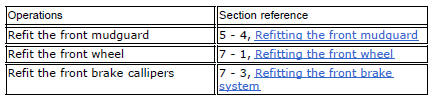
Warning
Do not ride with the front mudguard removed. The brake hoses are retained to the front mudguard to keep them from touching the wheel under braking.
 Overhauling the front forks
Note
It is advisable to loosen the top cap (14) when the fork is still fitted
to the motorcycle.
Note
The specific tools for the revision of the fork, are described in sect. 3
- 4, Specific too ...
 Steering head: steering
Screw
Steering head
Screw
Lower rh u-bolt
Lower lh u-bolt
Bearing
Screw
Sealing ring
Washer
Spacer
Washer
Nut
Washer
Screw
Bottom yoke
Dowel
Nut
Screw
Specia ...
Other materials:
Front brake lever
Pull the lever (1, fig. 94) Towards the twistgrip to operate the
front brake. The system is hydraulically assisted and you only
need to pull the lever gently.
The control lever (1, fig. 94) Features a dial adjuster (2, fig. 94)
For lever distance from the twistgrip on handlebar
adjustment.
...
Refitting the timing belts
Rotate the pulleys on the timing belt driveshaft until the timing mark on the
outer roller is aligned with the mark on the
clutch-side crankcase cover.
In this condition, the horizontal cylinder piston will be at top dead centre.
Install in the alternator cover seat the tool code 88713.20 ...
Display background colour (automatic adjustment)
Instrument panel background colour is set automatically
according to exterior lighting conditions.
When sensor detects "poor lighting" (night), it switches to
black background mode; vice versa when a "significant"
lighting is detected (day), it switches to white background
...