
Ducati Diavel Service Manual: Removal of the gear selector lever
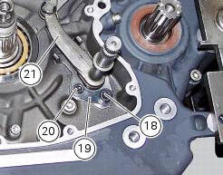
Unscrew and remove the fixing screws (18) and (20) of the complete gear selector lever (21) and collect the spacer (19).
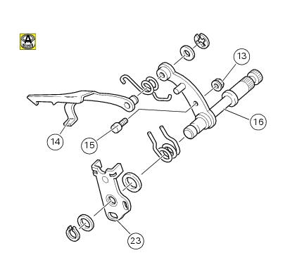
Remove the gearchange mechanism complete with the shaft, spring, and stop plate.
Important
Visually inspect the gear selector claw (14) for wear, particularly around the area where it contacts the selector drum.
If it proves necessary to change components, disassemble the gear selector lever as shown in the exploded view.
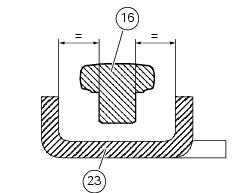
Reassemble the gear selector lever orienting the eccentric pin (15), suitably lubricated, in such a way that the lever arm (16) is positioned centrally with respect to the shoulders of the stop plate (23).
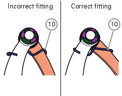
Check that the spring (10) is installed correctly as shown in the figure.
Tighten the nut (13) to a torque of 10 nm (min. 9 Nm - max. 11 Nm) (sect. 3 - 3, Engine torque settings).
 Gearchange mechanism
Return spring
Washer
Special screw
Gear pawl assembly
Interlock plunger holder
Sealing washer
Detent ball spring
Ball
Circlip
Selector claw return spring
Shim washer
Ring
...
 Disassembly of gear interlock plunger and pawl assembly
Unscrew the interlock plunger screw (5) and remove the seal (6), spring (7)
and the detent ball (8).
Unscrew the clutch-side crankcase half screw (3) and remove the pawl (4),
washer (2) a ...
Other materials:
Checking the coolant level
To the specified intervals in the "scheduled maintenance chart" (sect. 4 - 2)
Check the coolant level contained in
the expansion reservoir, on the right side of the vehicle.
The coolant level must be between the max. And min marks on the tank.
If the level is low, top up with the recommende ...
External components
Oil breather valve
O-ring
Sealing washer
Gear position sensor
Cylinder barrel/head stud
Nipple
By-pass spring
Plug
Plug
Aluminium gasket
Nut
Lock washer
Timing gear pair
Key
Key
O-ring
Screw
Locating dowel
Starter idler gear
Washer
Gear shaft
O-ring
...
Removal of the primary drive gear
Withdraw the clutch housing (1) complete with driven gear of the primary pair
(a).
Remove the inner spacer (2).
Remove the oil pump (d) (sect. 9 - 2.1, Removal of the oil pump).
Lock the primary pinion (b) with the holding tool 88713.3417 And loosen the
threaded ring nut (3) u ...