
Ducati Diavel Service Manual: Removal of the gearchange control
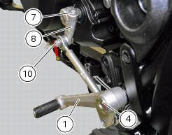
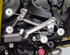
Loosen and remove the pivot screw (4) securing the gearchange pedal (1) and recover the washer (9) and the o-ring Seals (5).
Loosen and remove the screw (7) securing the gearchange lever (8) to the gear selector shaft.
Withdraw the lever (8) complete with the gearchange control assembly.
Note
Mark the position of lever (8) relative to the gear selector shaft.
To remove the lever (8) from the gearchange assembly, remove the screw (10) and slide the lever (8) out.
 Gearchange mechanism
Gearchange pedal
Bush
Rubber pad
Pin
O-ring
Gearchange lever tie-rod
Screw
Gearchange lever
Washer
Screw
Ball joint
Nut
Nut
Nut with left-hand thread
Lh ball joint
...
 Disassembly of the gearchange mechanism
Refer to the exploded view at the beginning of this section for indications
on disassembly and renewal of gearchange
components.
If the bushing (2) inside the pedal (1) needs replacing, grease t ...
Other materials:
High beam lights not working
Fault codes
The hi beam light on the (slave) dashboard flashes at 1hz frequency.
Wiring diagram
Location of elements on motorcycle
(A) injection relay; (b) etv relay (throttle valve operating engine); (c)
radiator fan relay; (d) hands free relay.
Fuses located at the rear left of the ...
Headlight control
This function allows you to reduce current consumption from
the battery, by automatically managing headlight switchingoff.
At key-on, the high beam and low beam lights are off.
When the engine is started, the low beam lights turn on
automatically; from this moment, "normal" operati ...
Removal of the intake manifold and coolant union
Loosen the clips (f) and remove the hoses (t).
Remove the manifolds (25) undoing the screws (21).
Loosen the clamp (a) and remove the hose (b). Remove the union (12) and
recover the seal (24).
...