
Ducati Diavel Service Manual: Disassembly of the gearchange mechanism
Refer to the exploded view at the beginning of this section for indications on disassembly and renewal of gearchange components.
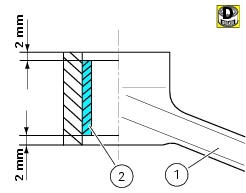
If the bushing (2) inside the pedal (1) needs replacing, grease the external surface and drive the new bushing into place using a press. The bushing must be seated 2 mm below the outer face of the pedal.
Warning
After working on the gearchange control, check the position of the gearchange pedal.
To adjust the gearchange pedal position, follow the instructions indicated in sec. 4 - 3, Adjusting the position of the gear change and rear brake pedals.
 Removal of the gearchange control
Loosen and remove the pivot screw (4) securing the gearchange pedal (1) and
recover the washer (9) and the o-ring Seals (5).
Loosen and remove the screw (7) securing the gearchange lever (8 ...
 Refitting the gearchange mechanism
Make sure that the gearchange linkage assembly (6) is installed with the ball
joint with a left-hand thread (a) facing the
lever (8).
Apply the recommended grease to the non-threaded surface of ...
Other materials:
Refitting the external components
Fit the cap (39) on spring (38) until it engages.
Mount ball (40), spring (38) with cap (39), washer (37) and screw (36) on the
chain side half-casing by starting the
screw into hole (f).
Note
The spring (38), with cap (39), must be oriented as shown.
Tighten the screw fully home to a torqu ...
Tubeless tyres
Front tyre pressure:
2.50 Bar (rider only) - 2.6 Bar (with passenger and/or bags)
rear tyre pressure:
2.50 Bar (rider only) - 2.6 Bar (with passenger and/or bags)
as tyre pressures are affected by changes in temperature
and altitude; check and adjust them whenever you are riding
in areas where ...
Deactivating the service indication on the dashboard
The message "serv" is displayed on the dashboard, indicating that the
motorcycle should be serviced in accordance with
the programmed maintenance plan. This indication is activated after the first
1000 km and thereafter at intervals of
12000 km.
After the scheduled service has been carried ...