
Ducati Diavel Service Manual: Removal of the generator cover
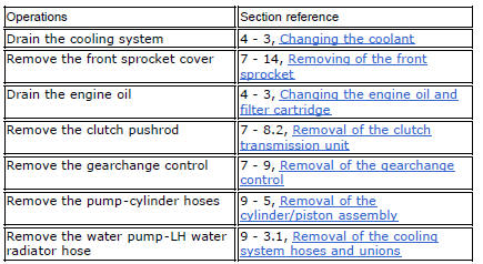
Note
This operation is described for an engine removed from the frame since all reassembly procedures are easier with the engine on the bench.
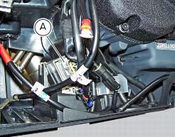
Disconnect the connector (a) from the generator cable.
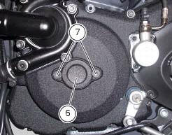
Unscrew the two retaining screws (7) of the centre cap (6) over the end of the crankshaft.
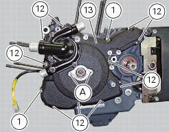
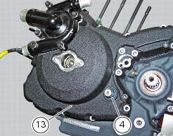
Loosen the screws (1) and (12) securing the generator cover (13).
Use tool number 88713.1749 And fix it to the holes (a) of the previously removed screws (7).
Turn the tool shaft slowly to separate the cover (13) from the lh crankcase half.
There is a seal (4) on the cover (13) in correspondence with the gearchange lever shaft that may be damaged when removing the generator cover.
Always check the condition of this sealing ring and renew it if damaged.
 Flywheel - alternator
Screw
Alternator stator
Plug
Sealing ring
O-ring
Cover
Screw
Aluminium gasket
Screw
Bracket
Locating bush
Screw
generator cover
Flange
Flanged nut
Plane washer
F ...
 Disassembly of the generator cover
Undo the three stator retaining screws (25) and the two retaining screws (9)
of the two cable grommet bracket (10) from
inside the generator cover.
Remove the stator (2) and the cable grommet br ...
Other materials:
Removal of the cooling system hoses and unions
Loosen the clips (21) that secure the radiator/thermostat sleeve (40) and the
radiator/plug sleeve (24) to the water
radiators.
Loosen clips (25) and (43) that secure the breather pipe (26) to the
radiator/plug sleeve (24) and to the left radiator.
Loosen the clips (34) securi ...
Refitting the side stand
Place the stand plate on the rear shock absorber support; bring adjuster (14)
in line with bracket (s) and start the screw
(12) in the nut behind the bracket (s).
Insert the screws (11), (3) and (10) fully home in this order, but do not
tighten.
Loosen the screw (12) with the relative nut ...
Indicator cons. Avg - average fuel consumption
This function indicates the "average" fuel consumption.
The calculation is made considering the quantity of fuel used and
the km travelled since the last trip 1 reset. When trip 1 is reset,
the value is set to zero and the first available value is shown on
the display 10 seconds afte ...