
Ducati Diavel Service Manual: Camshafts
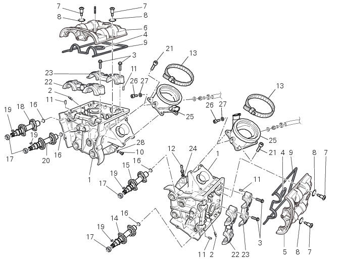
- Head
- Stud bolt
- Special screw
- Sealing washer
- Horizontal cylinder head cover
- Vertical cylinder head cover
- Special screw
- O-ring
- Head gasket
- Screw
- Pin
- Union
- Clamp
- Horizontal cylinder exhaust camshaft
- Horizontal cylinder intake camshaft
- Plug
- Sealing ring
- Vertical cylinder exhaust camshaft
- Key
- Vertical cylinder intake camshaft
- Screw
- Timing side support
- Opposite side support
- Sealing washer
- Intake manifold
- Screw
- Sealing washer
- sealing washer
Spare parts catalogue
Diavel abs cylinder head: timing system
Diavel abs vertical cylinder head
Diavel abs horizontal cylinder head
Diavel abs throttle body
Diavel carbon abs cylinder head: timing system
Diavel carbon abs vertical cylinder head
Diavel carbon abs horizontal cylinder head
Diavel carbon abs throttle body
Important
Bold reference numbers in this section identify parts not shown in the figures alongside the text, but which can be found in the exploded view diagram.
- Removal of the camshafts
- Checking the camshafts and supports
- Refitting the camshafts
- Removal of the intake manifold and coolant union
- Refitting the intake manifold and coolant union
 Refitting the timing covers
Locate vertical cylinder external cover (25), horizontal cylinder external
cover (3) and central external cover (1) by
starting the screws (4).
Apply the recommended threadlocker to the screws ( ...
 Removal of the camshafts
Unscrew and remove the screws (7) and the o-rings (8) from the cylinder head
covers.
Remove the cylinder head cover (6).
Remove the gaskets (4) and (9).
Repeat the same procedure fo ...
Other materials:
Passenger grabhandle
Passenger grabhandle (1, fig. 107) Is located inside the tail
guard; to take it out, remove the seat (see "removal of the
seat" on page 119), pull the knob (2, fig. 107) While taking out
the grabhandle (1, fig. 107) From its housing until it is fully
extended.
Warning
Before use, pu ...
Refitting the front wheel
When all the necessary inspections have been completed, refit the wheel as
follows.
Fit the spacers (3) and (9) to the seal rings on the sides of the wheel hub.
Install the complete wheel between the fork legs.
Lubricate the shank and thread of the wheel axle (10).
Take the pin ...
Inspection of the gear selector forks
Visually inspect the gear selector forks. Bent forks must be renewed as they
may lead to difficulties in gear changing or
may suddenly disengage when under load.
Use a feeler gauge to check the clearance of each fork in its gear groove.
If the service limit has been exceeded, check whether ...