
Ducati Diavel Service Manual: Refitting the filler cap
Position seal (18) in tank cap (10) as shown and reassemble following the removal procedure in the reverse sequence.
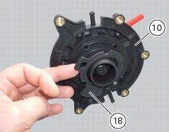
In particular tighten the screws (17) to a torque of 3 nm +/- 10% (sect. 3 - 3, Frame torque settings).
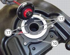
 Removal of the fuel tank filler cap
Remove tank covers (sect. 5 - 2, Removal of the fuel tank fairings).
Remove hoses (8) and (15) from the filler cap assembly (10).
Open the filler cap.
Unscrew the outer screws (17) securing ...
 Replacing the tank flange and fuel sensor
Loosen the screws (19) securing the fuel tank flange (20).
Remove the flange (20) from the tank (20).
Recover the seal (21).
Undo and remove the two fixing screws (g) and move the protectio ...
Other materials:
Removal of the rear brake calliper
Important
The brake manufacturer advises against any servicing of the internal
components of brake callipers or the master cylinder.
Incorrect overhaul of these critical safety components can endanger rider and
passenger safety.
Before removing the parts in question, you must first carry ou ...
Replacing the high and low beam bulbs
Before replacing a burnt-out bulb, make sure that the new
bulb complies with the voltage and wattage specified in the
"wiring diagram", page 179. Always test the new bulb
before refitting any parts you have removed.
Fig. 150 Shows the locations of the low beam bulbs (lo), high
beam ...
Resetting turn indicators not possible - accessing dashboard menu not
possible
Fault codes
Dds: no fault code displayed
Dashboard: no fault code displayed
Location of connections and components
Location of left hand handlebar switchgear set connection.
Pin numbering for wiring harness side dashboard connector.
Checks
Test turn indicator reset button function. Wh ...