
Ducati Diavel Owners Manual: Riding mode customisation
This function customises each riding style.
To access the function it is necessary to view the "setting"
menu page 48, using button (1, fig. 14) ?
or (2, fig. 14)
? select the "riding mode" function
and press the
reset button (12, fig. 12) To go to next page.
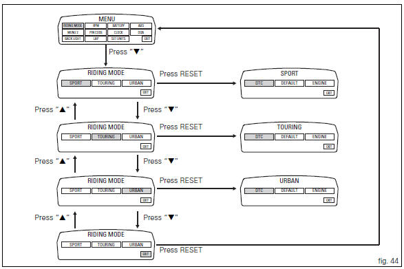
When accessing the function, the three riding modes appear
on the display; to customise the parameters, use button (1,
fig. 14)  or (2, fig. 14)
 to select the riding mode to
be changed and press the reset button (12, fig. 12) To
confirm.
The parameters that can be "customised" are "dtc" (ducati traction control) and "engine".
Any parameter change made is saved in the memory also after a battery-off.
To change the dtc parameters see the "dtc (ducati traction control)" paragraph page 52.
To change the engine parameters see the "engine (engine power control)" paragraph page 56.
The parameters set by ducati for each individual riding style can be restored with the "default" function.
To reset the "default" parameters see the "default (resetting ducati default parameters)" paragraph page 58.
 Note
Note
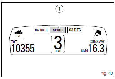
If the parameters have not been modified (customised) or are reset using the "default" function, when you quit the setting menu, in the "main" screen, the "background" indicating the riding style (sport, touring or urban) becomes blue (1, fig. 43).
 Warning
Changes should only be made to the parameters by people who are experts in motorcycle setup; if the parameters are changed accidentally, use the "default" function to reset the parameters.
 Setting menu
This menu is used to enable/disable and set some
motorcycle functions.
To access the "setting menu" press the button (2, fig. 14)
? for 3 seconds.
Note
When within this menu no ...
 Dtc (ducati traction control) setting function
This function allows you to customise the level of dtc
intervention (ducati traction control) or disable it for every
riding mode.
To access the function it is necessary to view the "setting ...
Other materials:
Replacing the high and low beam bulbs
Before replacing a burnt-out bulb, make sure that the new
bulb complies with the voltage and wattage specified in the
"wiring diagram", page 179. Always test the new bulb
before refitting any parts you have removed.
Fig. 150 Shows the locations of the low beam bulbs (lo), high
beam ...
The battery charging circuit and power distribution
On the diavel, the +15v (key on power) voltage does not come from a
conventional ignition key, but from pin 30 of the
hands free relay. This relay is switched to closed state by the hands free unit
when the latter enables power on for the
ignition and engine. The hands free relay receives +30v ...
Identification data
All ducati motorcycles have two identification numbers, for
frame (fig. 1) And engine (fig. 2).
Note
These numbers indicate the motorcycle model and
should be quoted when ordering spare parts.
...