
Ducati Diavel Service Manual: The battery charging circuit and power distribution
On the diavel, the +15v (key on power) voltage does not come from a conventional ignition key, but from pin 30 of the hands free relay. This relay is switched to closed state by the hands free unit when the latter enables power on for the ignition and engine. The hands free relay receives +30v voltage (battery voltage), protected by a general 30a fuse.
The three phase alternator has three windings (l1, l2, l3), connected to one another in a "triangle" or "delta" configuration. The electrical terminals r, s and t are connected to the voltage regulator.
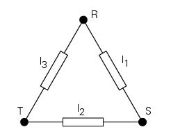
The drawing illustrates the "triangle" or "delta" configuration connection of the three windings of the three phase alternator.
The voltage regulator is constructed with specific electronic circuits (using mosfet instead of scr diodes) which limit operating temperature and, as a result, improve reliability. The regulator can withstand a maximum current of 50a (maximum current for the regulator used on sbk models is 35a) and has integrated waterproof electrical connections.
In the event of incorrect battery voltage (too low or too high), the message "battery" is shown in the service display. The dds also indicates if an excessively low or high battery voltage is detected (battery voltage diagnosis: high voltage, low voltage).
In the event of a battery charging circuit fault, check the following in the order given:
- Check the integrity of the electrical circuit connecting the alternator to the regulator and the regulator to the battery (to carry out these tests, disconnect the battery cables and check the state of the electrical connections and cables and check for short circuits). Also check the ground connection of the circuit on the engine
- At an engine speed of 2,500 rpm, the alternating charging voltage measured between t - r, t - s and r - s with the alternator disconnected from the voltage regulator ("zero load") must be between 40v and 50v. This measurement must only be made with a cold engine, and the alternator must only be disconnected from the voltage regulator in key off state. Replace the alternator if the voltage measured is incorrect.
- Check the insulation relative to ground of each of the three terminals (the resistance between r - ground, t - ground and s - ground must be infinite). If insulation is compromised, change the alternator windings
- The battery state of charge must be checked first before checking the function of the voltage regulator. Battery state of charge is ideal if the voltage measured between the battery poles is between 12.2V and 12.7V. The battery must be disconnected from the motorcycle electrical system for this measurement. After reconnecting the battery to the motorcycle electrical system, turn the engine on and maintain an engine speed of 3,000 rpm. At this engine speed, the voltage measured at the battery poles must be between 14v and 15v. If the battery voltage measured is incorrect, replace the voltage regulator
 Riding modes
The rider may select between four different riding modes (sport, touring,
urban and enduro) from the dashboard and via
the "turn indicator reset" button (3). Each riding mode contains settings for ...
 Ground connection locations
The negative cable, which is normally connected to the negative pole of the
battery, is fastened to the crankcase. From here, the cable
branches off and splits up within the electrical system to ca ...
Other materials:
Riding mode set indication
This function indicates the "riding style" set for the vehicle.
Three "riding modes" are available: sport, touring and urban.
Each riding mode can be changed using the "riding mode" function.
Note
The background of the riding mode (sport, touring or urban) is blue (1) if
currently set ridi ...
Traction control (dtc) deactivated
The activation of this (amber yellow) "warning" indicates
that dtc (ducati traction control) has been turned off.
Note
In this case, ducati recommends being very careful
when riding as the vehicle behaviour will be different in
comparison to when operating with the traction control
...
Changing bulbs
Changing the headlight bulbs
Before replacing a burnt out light bulb, ensure that the replacement bulb has
the same voltage and power rating as
specified for the lighting device in question (sect. 3 - 1.1, Lights/instrument
panel).
Warning
The halogen light bulbs in the headlight become hot ...