
Ducati Diavel Service Manual: Adjusting the clutch lever and front brake lever
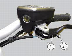
The clutch lever (1) is fitted with a span adjuster (2) which serves to alter the distance of the lever from the handlebar.
The lever distance can be adjusted through 10 clicks of the dial (2). Turn clockwise to increase lever distance. Turn the adjuster counter clockwise to decrease lever distance.
When the clutch lever (1) is operated, drive from the engine to the gearbox and the drive wheel is disengaged. Correct use of the clutch lever is very important in all riding situations, especially when moving off.
The position of the front brake lever (3) can be adjusted in the same way.
Warning
Any adjustment of clutch and brake levers must only be carried out when motorcycle is stationary.
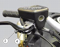
 Adjusting the throttle cable
The throttle grip in all steering positions must have free play, measured on
the periphery of the flange of the grip, of 1.5 -
2.0 Mm.
If necessary, adjust using the adjusters (1) and (2) loca ...
 Adjusting the position of the gear change and rear brake pedals
The position of the gear change and rear brake pedals in relation to the
footrests can be adjusted to suit the preferred
riding position.
To modify the gear change pedal position act in the foll ...
Other materials:
Clock setting function
This function sets the clock.
To access the function it is necessary to view the ""setting" menu", using
buttons (1) "s" or (2) "t" select the "clock"
function and press the reset button (3) to confirm.
In the following screen the message "setting" is highlighted in green (4); now,
press ...
Electrical power for lighting and signalling devices
The front and rear running lights consist of led units with light conduits.
As a result, the light source is not visible as the
light is diffused through the surface of the light conduit.
These two images illustrate the front and rear running lights with light
conduits.
The figure ...
Engaged gear indicator
This function displays the gears (1, fig. 25).
The instrument panel receives information and indicates the
engaged gear or "n" for neutral.
Note
In the case of a gear sensor "error", a dash "-" (not
flashing) will be displayed.
...