
Ducati Diavel Service Manual: Adjusting the throttle cable
The throttle grip in all steering positions must have free play, measured on the periphery of the flange of the grip, of 1.5 - 2.0 Mm.
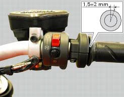
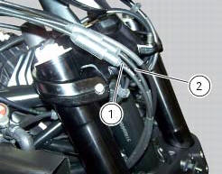
If necessary, adjust using the adjusters (1) and (2) located on the steering tube on the right side of the motorcycle.
Adjuster (1) adjusts the throttle opening control, while adjuster (2) adjusts the throttle closing control.
Note
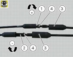
The throttle cables are distinguished by the writings in different colours on them:
- On the throttle opening cable (1) is a white writing;
- On the throttle closure cable (2) is a yellow writing.
Slip the rubber gaiters (3) off the adjusters and loosen the check nuts (4).
Adjust both adjusters by the same amount: turn clockwise to increase free play and counter clockwise to reduce free play.
When finished, tighten the counter nuts and refit the protection gaiters (3) to the adjusters.
Periodically check the condition of the outer cables of the throttle opening (1) and closing cables (2). The plastic covering should show no signs of pinching or cracking.
Lubricate the ends of the inner cables with the specified grease periodically to ensure they run freely.
Operate the control to check that the inner cable slides smoothly inside the outer cable: if you feel excessive resistance or stiffness, renew the cable.
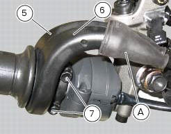
To lubricate the throttle grip, it is necessary to slide off the protection cover (a), loosen the screws (7) and remove the covers (5) and (6) of the throttle grip.

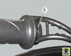
Lubricate the ends of the cable and the pulley (b) with the recommended grease.
When refitting the cover, make sure that the cables are correctly positioned in the pulley (b).
Place the covers (5) and (6) in the reference hole of the handlebar.
Fix covers (5) and (6) by tightening the screws (7) to a torque of 10 nm +/- 10% (sect. 3 - 3, Frame torque settings).
 Checking brake pad wear and changing brake pads
Warning
Brake fluid is corrosive and will damage paintwork. Avoid contact
with eyes and skin. In the case of accidental contact,
wash the affected area thoroughly with plenty of running water.
Im ...
 Adjusting the clutch lever and front brake lever
The clutch lever (1) is fitted with a span adjuster (2) which serves to alter
the distance of the lever from the handlebar.
The lever distance can be adjusted through 10 clicks of the dial (2). T ...
Other materials:
Overhaul of the gearbox
Check the condition of the front coupling dogs of the gears. They must be in
perfect condition and with no sign of wear on
the edges of the teeth.
The idler gears must rotate freely on their shafts.
When refitting, make sure the circlips are correctly positioned.
Check the needle roller ...
Abs disabling function
This function disables or enables the abs.
To access the function it is necessary to view the "setting" menu page 48, using
button (1, fig. 14) ?"
" or (2, fig. 14) ?"" select the "abs" function and
press the reset button
(12, fig. 12) To go to next ...
Removing of the rear footrests
The removal of the rear footrests is described for the right side but it is
the same for both.
Undo the pin (13) and remove the rh rear footrest (12) from the frame.
Recover washer (8) and the o-rings (9).
If necessary remove the rubber footrest (11) of the footrest (12).
...