
Ducati Diavel Service Manual: Checking brake pad wear and changing brake pads
Warning
Brake fluid is corrosive and will damage paintwork. Avoid contact with eyes and skin. In the case of accidental contact, wash the affected area thoroughly with plenty of running water.
Important
On handing over the motorcycle after changing the brake pads, inform the customer that the front brake must be used gently for the first 100 km to allow the pads to bed in completely.
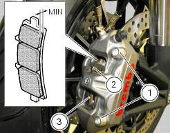
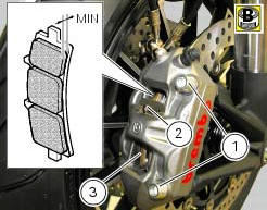
Checking front brake pad wear
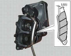
Check brake pads wear through the inspection hole in the callipers.
Change both pads if friction material thickness of even just one pad is about 1 mm.
Warning
Friction material wear beyond this limit would lead to metal support contact with the brake disc thus compromising braking efficiency, disc integrity and rider safety.
Remove the callipers by loosening the retaining screws (1) of the front brake calliper to the fork leg.
Remove the safety cotter pins (2).
Remove the worn pads (3).
Note
Change pads that have a shiny or "vitrified" appearance.
Insert new pads (3) with relevant safety cotter pins (2), push the calliper pistons fully inside their seats by forcing the pads apart.
Insert the front brake callipers into the discs.
Apply the recommended grease to the retaining screws (2).
Hand tighten the screws to secure the callipers to the fork legs.
Note
Operate the brake lever repeatedly so that the pads are firmly bedded in against the disc by the force of the brake fluid.
Check that the level in the master cylinder tank is not below the min mark.
If necessary, top up as follows.
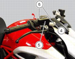
Turn the handlebar so that the reservoir is levelled.
Remove the cover (4) with membrane from the front brake fluid tank (5) by loosening the screws (6).
Top-up with specified fluid (sect. 3 - 2, Fuel, lubricants and other fluids) until reaching the max notch.
Hold the lever pulled towards the handgrip and simultaneously tighten the calliper screws (1) to a torque of 43 nm +/-10%(sect. 3 - 3, Frame torque settings).
Checking rear brake pad wear
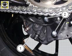
Remove the rear brake calliper (1) by loosening the screws (2).
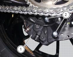
Check brake pads wear through the inspection hole in the callipers.
Change both pads if friction material thickness of even just one pad is about 1 mm.
Warning
Friction material wear beyond this limit would lead to metal support contact with the brake disc thus compromising braking efficiency, disc integrity and rider safety.
Change the brake pads as follows.
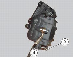
Remove the safety cotter pin (3) from the pad sealing pin (4).
Withdraw the brake pad retaining pin (4) and pull it out.
Force the brake pads apart to push the calliper pistons into their housings.
Release the worn pads (5) from the spring (6).
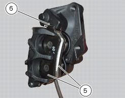
Insert the new pads (5) and the clip (6).

Slide in the pad retaining pin (3) and secure it in position with the safety cotter pin (2).

Force the pads apart to push the calliper pistons into their housings.
Insert the rear brake callipers in the disc.
Apply the recommended grease to the retaining screws (2).
Tighten the retaining screws (2) of the rear brake calliper to a torque of 44 nm +/-5% (sect. 3 - 3, Frame torque settings).
Operate the brake pedal repeatedly so that the pads are bedded in against the disc by the force of the brake fluid.
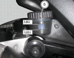
Check that the brake fluid level in the tank is between the min and max. Marks. If this is not the case, act on to the topup after unscrewing the tank cap (6).
Warning
Being the brake callipers a safety component of the vehicle, follow instructions under sect. 7 - 3, Refitting the front brake system, sect. 7 - 4, Removing of the rear brake control and pay attention, during refitting, to the tightening torque of 44 nm +/-5% (sect. 3 - 3, Frame torque settings) of the retaining screws (2) of the rear brake calliper.
 Adjusting the chain tension
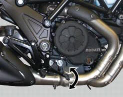
Make the rear wheel turn until you find the position where chain is tightest.
Set the vehicle on the side stand. Push down
the chain at the point of measurement and release. Measure the distance be ...
 Adjusting the throttle cable
The throttle grip in all steering positions must have free play, measured on
the periphery of the flange of the grip, of 1.5 -
2.0 Mm.
If necessary, adjust using the adjusters (1) and (2) loca ...
Other materials:
Wiring diagram colour codes
B blue
Bk black
Bn brown
G green
Gr grey
Lb light blue
O orange
P pink
R red
V violet
W white
Y yellow
Rear left fuse box (1) key
Rear right fuse box (2) key
...
Checking the idle speed
Check that the bike is provided with electronic control unit, oem intake and
exhaust systems, otherwise fit original
components.
Connect the inserts of the exhaust gas analyser code 88713.1010 To the outlets
on the exhaust pipes, using the fittings
(1).
Warning
Make sure that the thro ...
Description of the clutch assembly
The clutch is disengaged by a drive unit consisting of a thrust piston (c)
accommodated inside a small cap mounted to
the generator cover. This piston (c) pushes a pushrod (b), which runs through
gearbox primary shaft and operates the Pressure plate (4)
located on top of the clutch plate pack ...