
Ducati Diavel Service Manual: Removal the airbox and throttle body
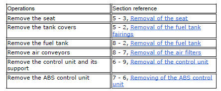
Loosen the screws (a) and remove the plate (b) that fixes the main wiring to the airbox.
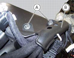
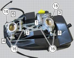
Undo the screws (17) and remove the air pressure sensors (9) with the support (19).
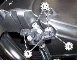
Release the hoses (c) of the air pressure sensors (9) from the tab (d) on the airbox.
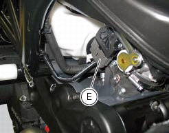
Operating on the right side of the vehicle, disconnect connector (e) from the aps sensor.
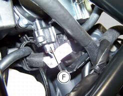
Operate on the vehicle lh side, disconnect connector (f) of the tps/etv motor.
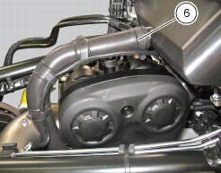
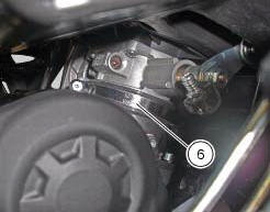
Loosen the clamp (6) that retains the blow-by pipe to the airbox
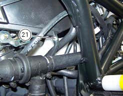
Loosen the clamp (21) that retains the drain hose to the airbox.
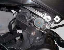
Loosen the clamps (6) that retain the airbox to the intake manifolds, and slide it out of its housing.
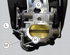
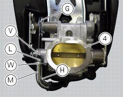
Operating on both throttle grip cables (h) and (m), loosen the nuts (l) and, turning the throttle body pulley (g), slide the two throttle grip cables (h) and (m).
Removal of the fuel injectors
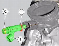
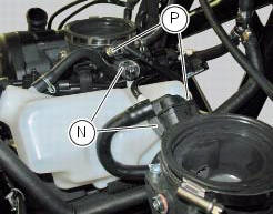
Operating on both intake manifolds, disconnect the connectors (n) that connect the main wiring to the injectors, loosen the fuel pipe retaining screws (p) and slide out the two injectors (3).

Refitting the injectors
Operate on both intake manifolds, check the presence of the o-rings (2) and (q) on injectors (3). Apply prescribed grease on o-rings (2) and (q) of injectors (3).
Insert the injectors in the relevant seats on the intake manifolds.
Important
To avoid damaging the o-rings, insert the injectors fully home on the intake manifolds by keeping them in line with the relevant seat.
Operate on both intake manifolds, position the fuel pipes fittings on the injectors.
Important
To avoid damaging the injectors o-rings insert the fittings by holding them in line with the injectors.
Keep the fittings pressed on the injectors, then start and tighten the screws (p) fully home.
Tighten the retaining screw (p) to a torque of 5 nm +/- 10% (sect. 3 - 3, Frame torque settings).
Connect the main wiring connectors (n) to the injectors.
Disassembly of the airbox - throttle body
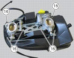
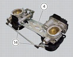
Undo the six screws (16).
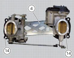
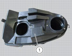
Remove the throttle body (4) from the filter box (1) with the intake manifolds (14).
Reassembly of the airbox - throttle body
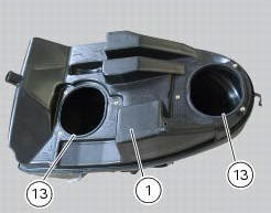
If removed, fit the seals (13) in the seats on the filter housing (1).
Note
To better insert the seals (13) use lubricant specific for rubber.
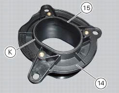
If removed, insert the gaskets (15) in the seats (k) of the intake ducts (26).
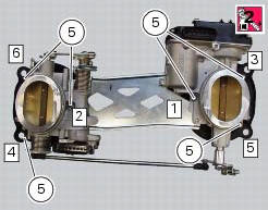
If removed, refit the intake ducts (14) on throttle body (4) and apply prescribed threadlocker to the screws (5) and tighten them to a torque of 3.5 Nm +/- 10% (sect. 3 - 3, Frame torque settings) following the sequence indicated in figure.
Important
After tightening, visually check that the seals (15), previously fitted on the intake funnels, are still in their seats, and that the intake funnels are perfectly coupled with the throttle body.
Fasten the throttle body (4) to the airbox (1).
Position and tighten the fixing screws (16) and tighten them to the torque of 5 nm +/- 10% (sect. 3 - 3, Frame torque settings), following the sequence indicated in figure
If removed, refit the throttle grip cable as indicated: insert the opening cable (m) and the closing cable (h) in the corresponding plate seats (w) on the throttle body (4) as shown in figure.
Note
The throttle cables are distinguished by the writings in different colours on them:
- On the opening throttle cable is a white writing;
- On the closure throttle cable is a yellow writing.
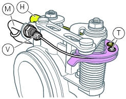
Insert the bolts (t) in the corresponding seats of the pulley. Keep oriented as shown in figure, fasten the cables (m) and (h) inserting the nuts (l).
Tighten the nuts (l) to a torque of 2.5 Nm +/- 10% (sect. 3 - 3, Frame torque settings).
Fit the dust caps (v) on the throttle cable sheaths terminals.
Check that the clip (21) of hose (26) is positioned as shown.
 Airbox - throttle body
Airbox
O-ring
Injector
Throttle body assembly
Screw
Clamp
Intake manifold
Screw
Pressure sensor
Screw
Clamp
Hose
Sealing washer
Intake manifold
Sealing washer
Scre ...
 Refitting the airbox and throttle body
Position the filter box (1).
Operate on the vehicle lh side, connect connector (f) of the tps/div motor.
Operating on the right side of the vehicle, connect connector (e) from the
aps sensor ...
Other materials:
Refuelling
Never overfill the tank when refuelling. The fuel level should
always be below the rim of the filler recess.
Warning
Use low-lead fuel with 95 octane rating at origin
minimum (see "top-ups" table, page 173).
Check that no fuel is trapped in the filler cap recess.
...
Tips for use on the track
We recommend level 8 be used for a couple of full laps (to
allow the tyres to warm up) in order to get used to the
system. Then try levels 7, 6, etc., In succession until you
identify the dtc intervention level that suits you best (always
try each level for at least two laps to allow the tyres t ...
Renewal of the headlight
Disconnect the headlight connectors (a) from the main wiring (refer to the
tables of paragraph "routing of wiring on
frame", sect. 6 - 1).
Loosen nuts (2) that fix the front optical unit to the bottom yoke, and
recover the washers (3).
Remove the complete front optical unit by sliding ...