
Ducati Diavel Service Manual: Refitting the airbox and throttle body
Position the filter box (1).
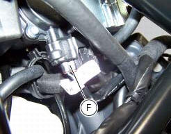
Operate on the vehicle lh side, connect connector (f) of the tps/div motor.
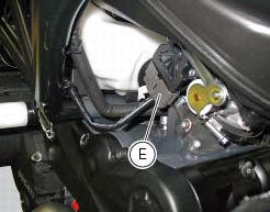
Operating on the right side of the vehicle, connect connector (e) from the aps sensor.
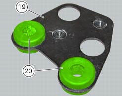
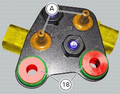
Check for the vibration dampers (20) on the map sensor supporting bracket (19).
Insert the spacers with collar (18) fully home onto the vibration dampers (20).
Note
Two spacers with collar (18) must be fitted on the upper side of the bracket (19) and the other two spacers with collar (18) must be fitted on the lower side of bracket (19).
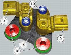
Set the map sensors (9) as shown on bracket (19) and fix them starting the screws (10).
Note
When fitting the map sensors, make sure to insert sensors (a) correctly into their seats in bracket (19) as shown.
Tighten the screws (10) to a torque of 10 nm +/- 10% (sect. 3 - 3, Frame torque settings).
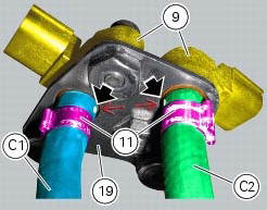
Insert a clip (11) on the longer hose (c1) and a clip (11) on the shorter hose (c2).
Fit the longer hose (c1) and the shorter hose (c2) on the map sensors (9) and position them so as to match the marks on longer hose (c1) and shorter hose (c2) with the arrows on the map sensor supporting bracket (19).
Fix the hoses (c1) and (c2) with the clips (11).
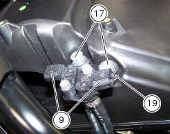
Refit the air pressure sensors (9) with the support (19) by starting and tightening the screws (17) to a torque of 5 nm +/- 10% (sect. 3 - 3, Frame torque settings).
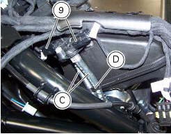
Block the hoses (c) of the air pressure sensors (9) with the tab (d) on the airbox.
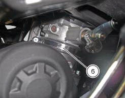
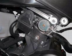
Position and tighten the clamps (6), as indicated, to the torque of 2.5 Nm +/- 10% (sect.3 - 3, Frame torque settings).
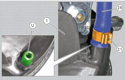
If the drainage pipe has been removed, fit clamp (21) onto drainage pipe (26).
Fit the drainage pipe (26) by inserting it fully home on fitting (u) on the filter box (1).
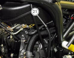
Orient the clamp (21) as indicated.
Fix the drainage pipe (26) by tightening the clamp (21).
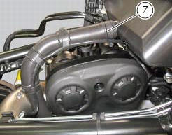
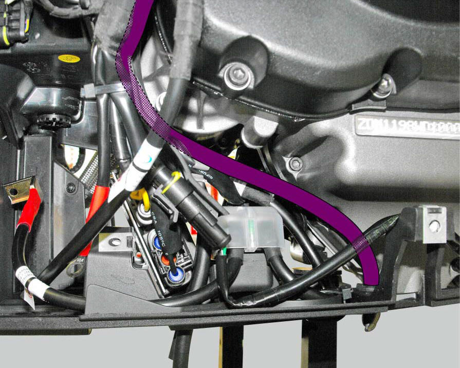
Refit the blow-by pipe to the airbox by tightening the clamp (z) to a torque of 5 +/- 10% (sect. 3 - 3, Frame torque settings).
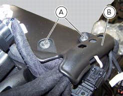
Refit the plate (b) retaining the main wiring to the airbox by tightening the screws (a) to a torque of 5 nm +/- 10% (sect.
3 - 3, Frame torque settings).
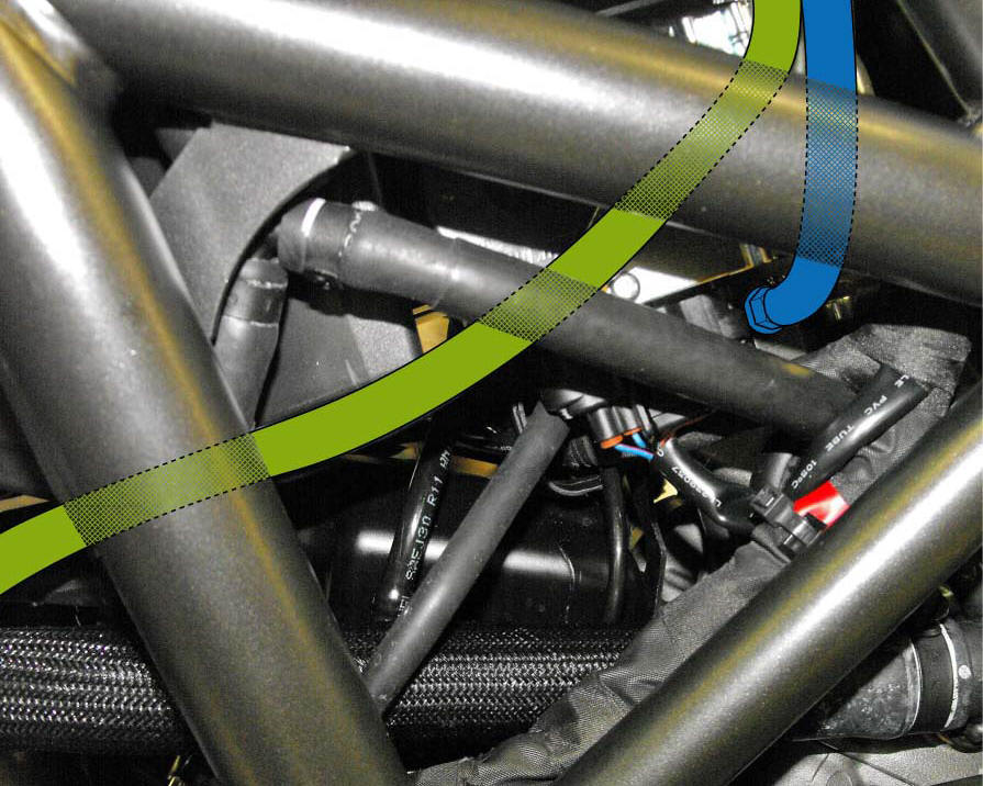
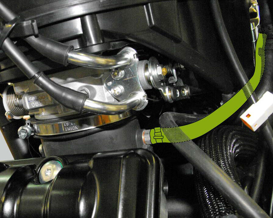
Positioning of the airbox drain hose
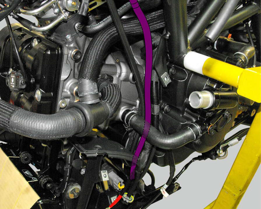
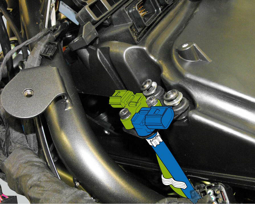
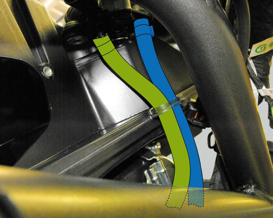
Positioning of the horizontal and vertical head air sensor hoses
 Removal the airbox and throttle body
Loosen the screws (a) and remove the plate (b) that fixes the main wiring to
the airbox.
Undo the screws (17) and remove the air pressure sensors (9) with the support
(19).
Release t ...
 Air intake
Air filter
Right air duct
Screw
Air temperature sensor
Screw
Left air duct
Sealing washer
Threaded insert
Spacer
Clamp
Breather hose
Spare parts catalogue
Diavel abs air ...
Other materials:
Checking brake pad wear and changing brake pads
Warning
Brake fluid is corrosive and will damage paintwork. Avoid contact
with eyes and skin. In the case of accidental contact,
wash the affected area thoroughly with plenty of running water.
Important
On handing over the motorcycle after changing the brake pads, inform the
customer that th ...
Overall dimensions (mm)
Weights
Weight in running order without fluids and battery: 210 kg.
Carrying full load: 400 kg.
Warning
failure to observe weight limits could result in poor
handling and impair the performance of your motorcycle, and
you may lose control of the vehicle.
Important
Do not use addi ...
Indicator air - air temperature
This function shows the external temperature.
Display limits: -39C - +124C
In the event of a sensor fault (-40C, +125C or disconnected), a string of
dashes "- - -" (not flashing) is displayed and
the "vehicle/engine diagnosis - eobd" light comes on.
Note
When the vehicle is stopped, the ...