
Ducati Diavel Service Manual: Appropriate diagnosis tools
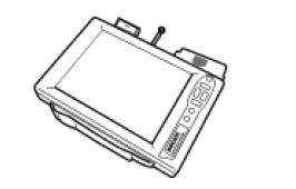
97900.0211 Dds (ducati diagnosis system) without cables
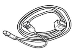
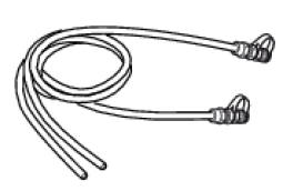
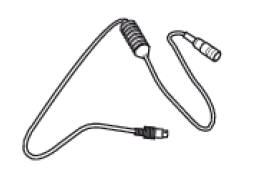
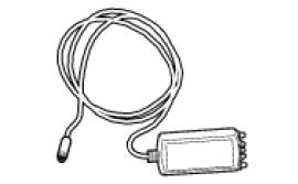
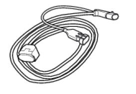
97900.0227 Power cable and diagnosis
97900.0222 Power cable and diagnosis 1060838 (measurement module)
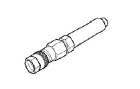
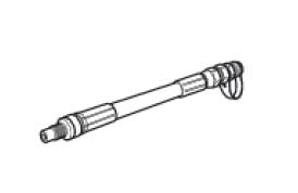
97900.0218 Vacuum sensor
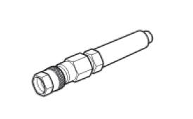
552.1.039.1A Pressure sensor
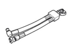
97900.0220 Pressure/vacuum tube
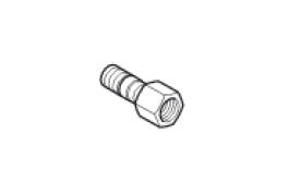
97900.0221 Union
97900.0228 Battery socket adapter
814.1.114.1A Oil pressure coupling
514.1.032.1A Auxiliary test cable
552.1.038.1A Cylinder compression cable m10 fitting

875.1.065.1A Oil pressure tube
97900.0230 Feeder
97900.0224 Feeder
88765.1371 Belt tensioning sensor
88765.1374 Belt tensioning sensor bracket
590.1.189.1A Fuel pressure tube
88765.1126 Clamp-type amperemeter
97900.0227S Can network diagnosis cable
 Specific tools for the frame
88713.1072 Drift to install half bearing in bottom yoke
88713.2562 Chain assembly tool
88713.1058 Wrench for steering shaft nut
88713.1062 Tool for installing steering head bearings ...

Other materials:
Removal of the clutch
Note
For clarity, the figures show the engine removed from the frame.
Undo the fixing screws (1) and remove the ring (2) and the springs (3) from
the pressure plate (4).
Slide the pressure plate (4) paying attention to the circlips (6).
Remove the clutch control pin (14) and the ...
Warranty
In your own interest, and in order to guarantee product
reliability, you are strongly advised to refer to a ducati dealer
or authorised service centre for servicing that requires any
particular technical expertise.
Our highly skilled staff have the tools required to perform any
servicing job ...
Refitting the tail light
Fit the spacers with collar (3) into the rear vibration dampers (2) located
on the gloves compartment (23).
Note
Two spacers (3) must be inserted inside and outside on the right side and
two spacers (3) must be inserted inside and
outside on the left side.
Insert the split vibration damp ...