
Ducati Diavel Service Manual: Reassembly of the timing pulleys
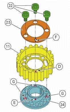
Fit the pulley (11) on the flange (24), aligning the timing mark (d) on the pulley with the timing mark on the (e) on the flange.
Install the washer (23) up against the pulley, aligning the timing notch (f) with the timing marks on the pulley and the flange.
Insert the three screws (22) in the threaded holes (g) of the flange.
Tighten the screws (22) to a torque of 10 nm (min. 9 Nm - max. 11 Nm) (sect. 3 - 3, Engine torque settings).

 Refitting the idler and tensioner pulley mounting studs
Apply the recommended threadlocker to the threads of the studs.
Insert the tensioner pins (12) on the cylinder heads, and tighten them using the
tool code 88713.1821.
Tighten the tensioner pin ...
 Refitting the cylinder heads pulleys/fixed tensioners
Check that the keyway on the end of the camshaft is in good condition and
without burrs.
Fit a woodruff key (b) in the keyway of each camshaft.
Fit the pulley (11) on the camshaft, inserti ...
Other materials:
Engine temperature sensor
Introduction
The engine control system on the diavel uses a sensor that measures the
temperature of the coolant (engine
temperature). This sensor has a resistance of ntc type (negative temperature
coefficient), that reduces its own value
when the temperature increases. The engine temperature ...
Tester power supply
The dds (1) part number 97900.0215 Can be powered from the vehicle as
follows:
From the mains power supply: by connecting the power supply connector
(n) to the network power supply (2) part no.
97900.0224;
From the motorcycle: connecting the corresponding cables (see paragraph
...
Refitting the clutch transmission unit
Position pipe (4) on the clutch slave cylinder (r).
Position the two seals (19) and tighten the screw (18) to a torque of 23 nm +/-
10% (sect. 3 - 3, Frame torque settings).
Refit the bleed valve (17) and the dust gaiter (16).
To position the pipe retaining clamps (4) refer to the table on ...