
Ducati Diavel Service Manual: Checking the engine timing
Set the engine to the configuration described for the "checking and adjusting the valve clearances", previously indicated.
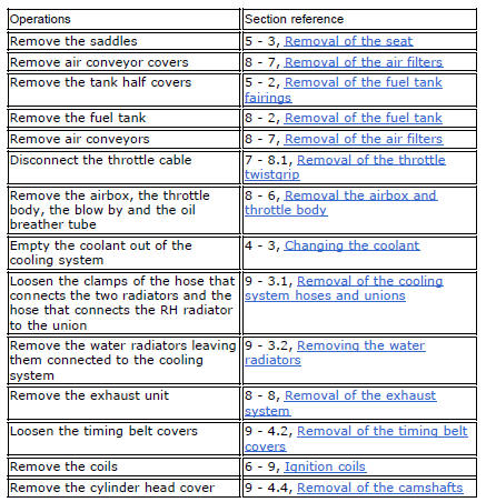
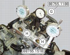
Install tool 88765.1188 (G) in the spark plug bore to determine the piston tdc, the gauges (h) on the tool 88765.1518 And the timing check tool (degree wheel (l) 88713.0123 With graduated disk).
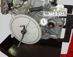
Set the opening valve clearance to zero when the camshaft is in its rest position by fitting a feeler gauge between the upper rocker arm and the opening shim.
Check that in this condition the camshaft can rotate. If it moves stiffly, use a thinner feeler gauge.
In this condition, with the piston of the horizontal cylinder at tdc with the valves fully closed as confirmed by the reading on gauge (g), set the gauges (h) to zero.
Set the tension value of the belts as described at sect. 6 - 11, Checking and adjusting timing belt tension.
Turn the degree wheel (l) counter clockwise until the gauge dial (h), on the exhaust side, shows a lift of 1 mm. Check that the value of the angular displacement read on the degree wheel (l) is as specified in (sect. 3 - 1.1, Timing system/valves).
Continue to rotate in the same direction until you obtain a lift of 1 mm on the intake side. Check the angular value on the degree wheel.
Continue to rotate until you obtain an intake valve lift of 1 mm on the gauge (h), during closure of the valve for the compression stroke. Check the angular value with the prescribed one (sect. 3 - 1.1, Timing system/valves).
Continue to rotate the degree wheel (l) counter clockwise until you obtain a lift of 1 mm of the exhaust valve, when opening or closing the valve.
Check the angular displacement value against the specified value.
Repeat the procedure for the vertical cylinder.
A tolerance of +/- 3 is allowed in the values detected with the described procedure regarding the prescribed ones (sect. 3 - 1.1, Timing system/valves).


Remove the installed tools to check timing. Then tension the belts to the value of the prescribed operation, as described at sect. 6 - 11, Measuring the timing belt tension values.
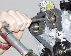
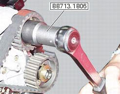
In case of values different from the described ones (sect. 3 - 1.1, Timing system/valves), loosen the fixing screws (m) of the timing pulley and correct the value detected by turning the ring nut of the timing shaft with the supplied wrench with code 88713.1806.
Lock the three retaining screws (m) of the timing pulley to the specified torque of 10 nm (min. 9 Nm - max. 11 Nm) (sect. 3 - 3, Engine torque settings) and mark the new position of the components.
Refit the components removed in the procedure.
 Checking valve lift
Set the engine to the configuration described for the "checking and adjusting
the valve clearances", previously indicated.
Position the tool 88765.1518 On the cylinder head: the part marked "a" s ...
 Timing system
Central external cover
Air filter
Horizontal cylinder timing belt cover
Screw
Filter support
Screw
Washer
Nut
Tensioner pulley assembly
Circlip
Camshaft pulley
Tensioner p ...
Other materials:
Removal of the shock absorber support
Remove the rear brake master cylinder (sect. 7 - 4, Removing of the rear
brake control).
Remove the rear shock absorber (see removal of the rear shock absorber of this
section).
Loosen the screws (2) and (7) and their nuts (35).
Remove the side stand (sect. 7 - 16, Removing of the ...
Removing the electrical components support
Remove the following elements located inside the electrical components
support:
The battery fixing bracket (4) and the battery (14) as specified under
section 6 - 2, battery;
The voltage regulator (3) as specified under section 6 -
2,rectifier-regulator;
The solenoid starter (18) ...
Inspection of the gear selector forks
Visually inspect the gear selector forks. Bent forks must be renewed as they
may lead to difficulties in gear changing or
may suddenly disengage when under load.
Use a feeler gauge to check the clearance of each fork in its gear groove.
If the service limit has been exceeded, check whether ...