
Ducati Diavel Owners Manual: Clock setting function
This function sets the clock.
To access the function it is necessary to view the "setting" menu page 48, using
button (1, fig. 14) ?"
"or (2, fig. 14) ?" "select the "clock"function and
press the reset button
(12, fig. 12) To confirm.
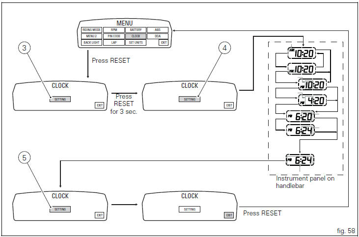
In the following screen the message "setting" is highlighted in green (3, fig. 58); Now, press the reset button (12, fig. 12) For 3 seconds to edit the time displayed on the instrument panel on handlebar, and the "settin"h indication highlighting becomes grey (4, fig. 58).
Clock setting
On entering this mode, the message "am"will flash; if you press the button
(2, fig. 14) ?" " "pm"flashes; if you
press the button (2, fig. 14) ?" "you
"you
will return to the
previous step (if it is 00:00, when switching between "am"
to "pm", 12:00 will be displayed).
Pressing button (1, fig. 14) ?" "
"
accesses the hour setting
mode; the hours start to flash.
Each time you press the button (2, fig. 14) ?" ",
",
the digit will
increase by 1 hour; if the button is held pressed down (2, fig.
14) ?" "the digit will increase by 1
hour every second (when
the button is held depressed, the hours do not flash).
Pressing button (1, fig. 14) ?" " gives
access to the minute
setting mode; minutes start to flash.
Each time you press the button (2, fig. 14) ?" ",
",
the digit will increase by 1 minute; holding down the button (2, fig. 14) ?" ",
",
the digit will increase by 1 minute each second; if the button is held depressed
(2, fig. 14) ?" " for over 5 seconds,
minutes will increase by 1 minute every 100 m (while the button is held
depressed (2, fig. 14) ?" ",
",
the
seconds will not flash).
If you press button (1, fig. 14) ?" "setting
is completed and
the instrument panel on tank display "settin"h item is
again highlighted in green (5, fig. 58).
To exit, select "exit"and press the reset button (12, fig. 12).
 Note
Note
In case of a battery is cutoff, when the voltage is restored and at the next key-on, the clock is always reset (it starts automatically from 00:00).
 Battery voltage indicator (battery)
This function describes the battery voltage indicator.
To access the function it is necessary to view the "setting" menu page 48, using
button (1, fig. 14) ?"" or (2, fig.
1 ...
 Units of measurement modification function
This function allows you to change the units of measurement
of the displayed values.
To access the function it is necessary to view the "setting" menu page 48, using
button (1, fig. 14 ...
Other materials:
Gearchange mechanism
Return spring
Washer
Special screw
Gear pawl assembly
Interlock plunger holder
Sealing washer
Detent ball spring
Ball
Circlip
Selector claw return spring
Shim washer
Ring
Nut
Selector drum control fork
Gearchange lever pin
Shaft with gearchange lever arm
Gearch ...
Timing system
Central external cover
Air filter
Horizontal cylinder timing belt cover
Screw
Filter support
Screw
Washer
Nut
Tensioner pulley assembly
Circlip
Camshaft pulley
Tensioner pin
Idler pulley assembly
Timing belt
Nut
Key
Spacer
Camshaft pulley
Driveshaft pulley ...
Moving off
Disengage the clutch by squeezing the clutch lever.
Push down the gear change lever firmly with the tip of
your foot to engage first gear.
Raise the engine revs by turning the throttle twistgrip
while gradually releasing the clutch lever. The motorcycle
will start moving.
Release the ...