
Ducati Diavel Service Manual: Overhauling the rear swingarm
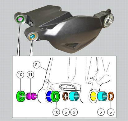
Inside the swingarm (8), in correspondence with the pivot point on the frame, there is a pair of ball bearings (10) and a spacer (11) on the rh side, and a pair of roller bearings (6), with sealing rings (5), on the lh side.
To change the bearings, proceed as follows.
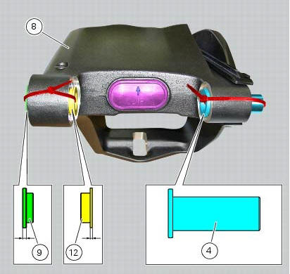
Remove the shims (12) and (9) from the right-hand side of the swingarm (8) and refit the bush (4) from the left-hand side.
Remove the ball bearings (10), sealing rings (5) and roller bearings (6) with a suitable punch and press. Support the swingarm and take care not to damage the bearing bores.
Important
Once removed, the bearings (10), sealing rings (5) and roller bearings (6) must not be reinstalled.
Heat the entire swingarm up to 150 C while supporting its weight adequately.
Apply recommended grease to the swingarm bearings seat.
Note
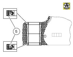
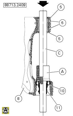
Upon reassembly the seals (5) must be oriented so that the plane side is faced outwards and the writings on the roller bearings (6) must be faced up.
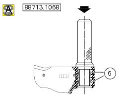
Insert the new roller bearings (6) in the punch tool with code 88713.1068 And install them into the bore on the left-hand side of the swingarm, working from the outside.
Drive them in until the tool is fully seated against the swingarm.
Use the same tool to fit the new sealing rings (5), positioned as shown in the sectional view, so that they seat against the newly installed roller bearings.
To install the ball bearing (10) you will need the tool with part no. 88713.2409 With:
(A) - drift for internal bearings; (b) - drift for external bearings; (c) - guide pin.
Apply recommended grease to the swingarm bearings seat.
Note
Upon bearings (10) reassembly they must be feature the writings outwards.
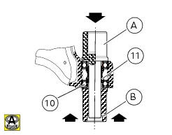
Fit a new bearing (10) and the internal spacer (11) onto the punch tool (a) and install it on the inner side of the swingarm rh mounting.
Insert the guide pin (c) into the previously mounted roller bearings and insert the other end in the bore in the tool (a).
Drive the bearing (10) fully into the swingarm.
Fit the other new bearing (10) at the outer end of tool (a).
Using tool (a) as a stop, use tool (b) to drive the external bearing up against spacer (11): remove the tools.
Refit the shims (12) and (9) from the right-hand side of the swingarm (8) and refit the bush (4) from the left-hand side.
Note
The spacer (9) with the larger external collar goes on the external side of the swingarm, whereas the spacer (12) with the smaller external collar goes on the inside.

 Removal of the swingarm
Before removing the parts in question, you must first carry out the following
operations:
Remove the rear wheel eccentric hub as described in chapter "removal of the
rear wheel eccentric hub ...
 Refitting the swingarm
Apply the recommended threadlocker to the screws (7).
Install the lower chain guard (15) on the swingarm (8), fastening it with the
screws (7): tighten the screws (7) to a torque
of 4 nm +/- 10% ...
Other materials:
Menu 2 on/off function
This function turns off and back on the menu 2.
If menu 2 is disabled, the functions for average fuel consumption (cons.Avg),
instantaneous fuel consumption (cons.),
Average speed (speed avg), trip time (trip time) and air temperature (air) will
no longer be displayed in the "main
screen". ...
Instrument panel diagnosis
This function identifies any abnormal vehicle behaviours.
The instrument panel activates any abnormal vehicle
behaviours in real time (errors).
At key-on (at the end of the check) one or more "errors"
are displayed in red (only if they are active).
When an "error" is t ...
Removal of the front brake system
Note
For the abs front braking system, also refer to sect. 7 - 5, Abs system
operating information, sect. 7 - 6, System
components, sect. 7 - 7, Abs components maintenance.
Undo the special screw (3), collect the sealing washers (4), and release the
front brake master cylinder assembly (1 ...