
Ducati Diavel Service Manual: Removal of the swingarm
Before removing the parts in question, you must first carry out the following operations:
Remove the rear wheel eccentric hub as described in chapter "removal of the rear wheel eccentric hub and rear wheel shaft" of this section.
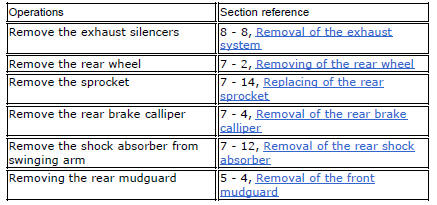
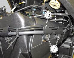
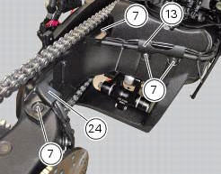
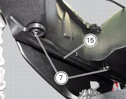
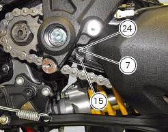
Loosen screws (7) and remove the hose grommets (13), (15) and (24).
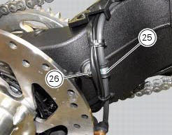
Release the rear brake hose, the rear speed sensor cable, and the rear wiring from the swingarm, by loosening the screws (26) and retrieving the cable grommets (25).
You can check the play in the swingarm bearings while the swingarm (8) still installed on the motorcycle frame.
Grasp the rear of the swingarm (8) and try to move it in the four directions shown by the arrows.
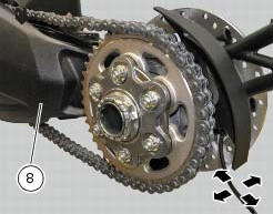
Any abnormal movement is a sign of worn bearings that could cause instability when riding.
To check the free play of the support bearings, refer to sect. 7 - 1, Wheel bearings.
Once the play in the swingarm bearings has been checked, the swingarm (8) may be removed from the motorcycle.
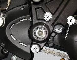
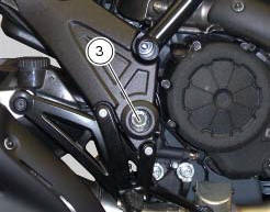
Keep the swingarm shaft (1) blocked with the screws (3) on the bike lh side and loosen at the same time the screw (3) on the opposite side: keep washer (2).
Using the punch 88713.1074, Fully extract the swingarm pivot.
Remove the swingarm (8) assembly from the frame.
Inspecting the swingarm pivot
Before refitting the swingarm pivot shaft (1), check it carefully for distortion.
Roll the pin on a reference surface and measure maximum distortion using a feeler gauge (sect. 3 - 1.1, Rear wheel).
 Refitting the rear wheel eccentric hub and rear wheel shaft
Refitting is the reverse of removal, with attention to the following points.
If the calliper bracket locating pin (14) was removed, apply the recommended
threadlocker on reassembly.
Tighten th ...
 Overhauling the rear swingarm
Inside the swingarm (8), in correspondence with the pivot point on the frame,
there is a pair of ball bearings (10) and a
spacer (11) on the rh side, and a pair of roller bearings (6), with sealing ...
Other materials:
Tips on how to select the sensitivity level
Warning
The 8 level settings of the dtc were calibrated using
tyres of the same make, model and size as those originally
fitted to the motorcycle.
The use of tyres of different size to the original tyres may
alter the operating characteristics of the system.
In the case of minor differenc ...
Refitting the fuel tank
If the fuel tank has been disassembled into its component parts, reposition
all the parts as shown in the exploded view.
In particular:
tighten the screws (13) to a torque of 5 nm +/-10% (sect. 3 - 3, Frame torque
settings).
Refit the tank by inserting its rear side into the pin on the ...
Symbols - abbreviations - references
To allow quick and easy consultation, this manual uses graphic symbols to
highlight situations in which maximum care is
required, as well as practical advice or information. Pay attention to the
meaning of the symbols since they serve to avoid
repeating technical concepts or safety warnings th ...