
Ducati Diavel Service Manual: Disassembly of rear shock absorber - rocker arm - linkage assembly
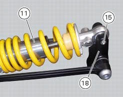
Undo the screw (15) and remove the rear shock absorber (11) from the rocker arm (18).
Undo
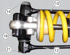
Undo the screw (14) and the nut (21) and remove the linkages (10) and (12) from the rocker arm (18).
The rocker arm movement is obtained by needle roller bearings (9) rotating on a spacer (13); two seals (8) are placed at the outer ends and keep the lubricant inside the roller cages.
Remove the inner spacer (13), the seals (8) and the needle roller bearings (9) using a suitable punch.
Important
Take care not to damage the bearing housings on the rocker arm while driving out the bearings. Once removed, the seals (8) and needle roller bearings (9) may not be refitted.
 Removal of the rear shock absorber
Loosen the screws (22) and remove the assembly (34) from the frame.
Loosen the screws (27) and remove the tank unit (s) of the shock absorber
from the support (19).
Hold the lh bush (6 ...
 Reassembly of rear shock absorber - rocker arm - linkage assembly
Once the needle roller bearings (9) have been removed from the rocker arm
(18), upon reassembly fit a new needle roller
bearing (9) on drift part no. 88713.1071 And lubricate with recommended greas ...
Other materials:
Clutch lever
Lever (1) disengages the clutch. It features a dial adjuster (2)
for lever distance from the twistgrip on handlebar.
The lever distance can be adjusted through 10 clicks of the
dial (2). Turn clockwise to increase lever distance from the
twistgrip. Turn the adjuster counter clockwise to decrea ...
Introduction to the "hands free" system
The hands free system allows the rider to start the engine without physically
using the ignition key. The ignition key
merely has to be in the vicinity of the motorcycle, such as in the rider's
pocket, for example, in order to use the vehicle.
Compared to the standard ignition switches the h ...
Refitting the crankshaft/connecting rod assembly
Install the connecting rod assembly (6) and (2) in the crankcase, carry out
the shimming and crankcase half reassembly
procedure as described in sect. 9 - 9.2, Reassembly of the crankcase halves.
Important
Make sure that the connecting rods (2) are correctly positioned in the
cylinders. Incor ...