
Ducati Diavel Service Manual: Reassembly of structural components and the frame
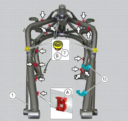
Check for the nuts with clips (8).
Apply recommended grease on the threads of the adjusters (4) and the ring nuts (5) having care not to have grease on the surface (c) of the adjusters.
Tighten the adjusters on the ring nut side opposite to that featuring flats until bringing the surfaces as close as possible as shown.
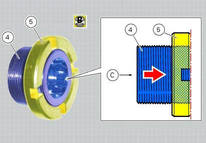
Start (form the frame external side) the adjusters (4) in the bushes (d) on frame (1).
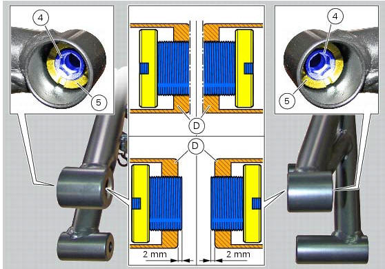
Tighten to torque of 0.6 Nm +/- 10% (sect. 3 - 3, Frame torque settings) the adjusters (4), until they come out (on the opposite side) of at least 2 mm, as indicated.
Note
If at the specified torque the adjusters should not tighten properly, maybe the adjusters or the frame could be nonconforming.
Loosen the adjusters (4) until bringing the surfaces as close as possible to the bushes internal profiles (d), as shown.
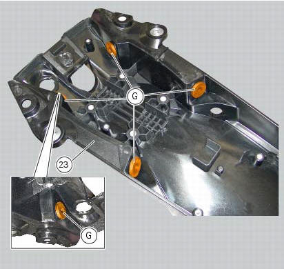
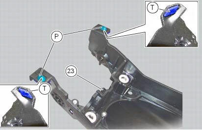
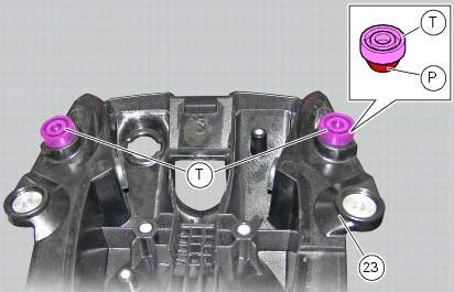
Check for the presence of rubber blocks (g) on the tray (23).
Note
In case of difficulties upon reassembly of the vibration damping pads (g), it is recommended to use specific lubricant suitable for rubber.
Check for the presence of the rubber pads (t) on the tray (23).
The pads are correctly fitted if the protrusions (p) come out completely on the insertion opposite side.
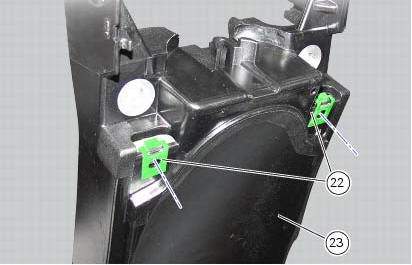
Check for the presence of clips (22) and make sure they are fitted aligned with the holes in the gloves compartment (23) front side, as shown in the figure.
Note
The threaded holes of the clips (22) must be perfectly aligned with the holes on the gloves compartment.
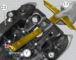
If removed, insert the rear handgrab (17) fully home through the opening in the gloves compartment (23) as shown.
Note
While inserting the component, make sure to push it past the stop tab (y) without hitting it.
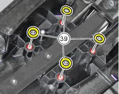
Position the spacers (39) at the threaded inserts of the gloves compartment (23).
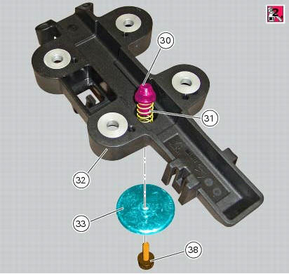
If previously removed, insert pin (30) on spring (31); position the spring (31), together with the pin (30), in the specific seat of the handle (32) guide as indicated.
Insert the screw (38) on knob (33), by orienting the latter as indicated.
Apply prescribed threadlocker on the screw thread (38).
Push down the pin (30) and start the screw (38) on the opposite side.
Tighten the screw (38) to a torque of 5 nm +/- 10% (sect. 3 -3, Frame torque settings).
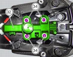
Fit block (32) starting the screws (34) and making sure that the spacers (39) stay in place, centred with the relative threaded inserts.
Tighten the screws (34) to a torque of 20 nm +/- 5% (sect. 3 - 3, Frame torque settings), following a cross-pattern sequence.
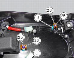
Place the clips (26) on the tabs (j), fix them starting the screws (25) and tighten the screws to the torque of 2 nm +/- 10% (sect. 3 - 3, Frame torque settings).
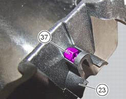
Position the nut (37) in the suitable seat on the compartment (23).
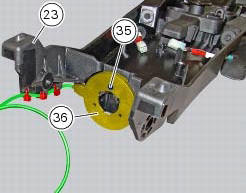
Fit the immobilizer antenna (36) as shown and tighten the screw (35) on nut (37) to the torque of 2 nm +/- 10% (sect. 3 - 3, Frame torque settings).
Fix the immobilizer antenna wire to the compartment using the three self-locking tie wraps.
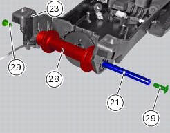
Start the screw (29) on the pin (21).
Place the tank supporting pad (28) in its seat on the gloves compartment (23) and insert the pin until bringing the screw (29) you started before fully home against the compartment (23).
Start the other screw (29) on the free end of the pin (21) and tighten the screw to a torque of 10 nm +/- 10% (sect. 3 - 3, Frame torque settings) holding the screw (29) on the opposite side.
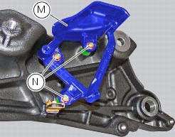
Check the presence of the clip (e) on the left plate of the rear subframe (3).
If the blackbox had been removed from the left plate of the rear subframe (3), on refitting start the silent blocks (f) on the plate (3) and tighten them until fully home. Insert the safety washers (l) on the threaded pins of the silent blocks (f).
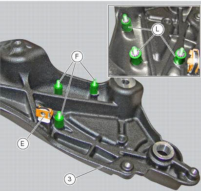
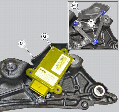
Fit the blackbox supporting bracket (m) starting the nuts (n). Tighten the nuts (n) to a torque of 2 nm +/- 10% (sect. 3 - 3, Frame torque settings).
Set the blackbox (q) on the stud bolts (r) of the blackbox supporting bracket (m).
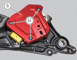
Fit the blackbox cover (s) starting the screws (u) and tighten the screws (u) to the torque of 3 nm +/- 10% (sect. 3 - 3, Frame torque settings).
 Checking the frame
Check the dimensions of the frame against the dimensions shown here to
determine whether it needs to be realigned or
renewed.
Important
Damaged frames must be changed, not repaired. Any work carr ...
 Reassembling the frame and the lateral footrests
Apply the recommended grease to the thread of the pins (9) and of the nuts
(8).
Place the frame (1) and the brackets (2) and (3) on the engine block. Start the
pins (9) by holding the nuts (8) ...
Other materials:
Indication of range reached for service
When service coupon threshold is achieved, upon every key-
on the system displays the indication of the type of
intervention that is required (oil service or desmo
service).
The (red) warning is activated as a large icon for 10 seconds
upon every key-on (1, fig. 33) Then as a small warning th ...
Refitting the handlebar
Position the handlebar (4) so that the external lower corner of the marks (a)
on the handlebar matches the upper internal
corner of the lower u-bolts (b) as shown.
Apply the recommended grease to the threads and undersides of the heads of
the screws (3).
Important
Position the upper u-bo ...
Symbols
Ducati motor holding s.P.A. Advises you to read this manual
carefully in order to become familiar with your motorcycle. If
in doubt, please contact a ducati dealer or authorised
service centre. The information contained herein will prove
useful on your trips - and ducati motor holding s.P.A. Wis ...