
Ducati Diavel Service Manual: Frame inspection
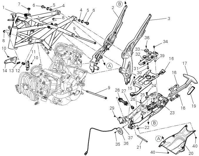
- Frame
- Rh subframe
- Lh subframe
- Grub screw
- Nut
- Special screw
- Rubber pad
- Nut
- Special screw
- Screw
- Left-hand bracket
- Hose clip
- Hose clip
- Right-hand bracket
- Special screw
- Cover
- Handgrab
- Slider
- Reflector (rear)
- Splashguard
- Pin
- Clip nut
- Tool tray
- Screw
- Screw
- Base
- Cable grommet
- Rubber support
- Screw
- Pin
- Spring
- Block
- Nut
- Screw
- Screw
- Immobilizer antenna
- Nut
- Screw
- Washer
- Screw
Spare parts catalogue
Diavel abs frame
Diavel abs rear subframe
Diavel carbon abs frame
Diavel carbon abs rear subframe
Important
Bold reference numbers in this section identify parts not shown in the figures alongside the text, but which can be found in the exploded view diagram.
- Disassembly of structural components and the frame
- Removal of the tool tray
- Removing the frame and the lateral footrests
- Checking the frame
- Reassembly of structural components and the frame
- Reassembling the frame and the lateral footrests
- Reassembly of the tool tray
 Refitting the side stand
Place the stand plate on the rear shock absorber support; bring adjuster (14)
in line with bracket (s) and start the screw
(12) in the nut behind the bracket (s).
Insert the screws (11), (3) and ...
 Disassembly of structural components and the frame
Before carrying out dimensional checks on the frame, you must remove all the
superstructures fitted, referring to the
removal procedures outlined in the sections of this manual.
The rear subfram ...
Other materials:
Removal-refitting of the engine assembly
Screw
Special screw
Nut
Screw
Swingarm pivot
Special screw
Washer
Spare parts catalogue
Diavel abs frame
Diavel abs swingarm
Diavel carbon
abs
frame
Diavel carbon
abs
swingarm
Important
Bold reference numbers in this section identify parts not shown in the
figures a ...
Disassembly of the clutch cover
Remove the plug (14) and its o-ring (13), the plug (17) and its o-ring (15)
from the cover.
Undo the fixing screw (16) of the inner cover (19).
Remove the inner cover (6) and soundproofing panel (18).
Remove the circlip (10) and withdraw the shim (9) and the sealing ring (8).
The dri ...
Removal of the front mudguard
Undo the screw (7) and remove the front brake lines (a) from the hose grommet
(4).
Undo and remove the special retaining screws (5): keep the spacers (6).
Remove the front mudguard (1).
Warning
The version provided with carbon mudguards features nylon washers
instead of the spacers (6) ...